


21
SERVICE AND ADJUSTMENTS
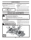
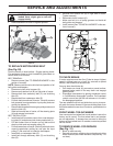
FIG. 27
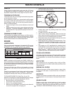
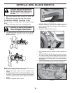
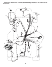
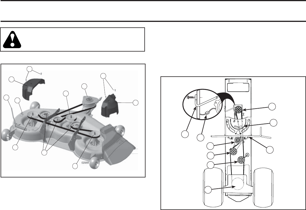
TO REPLACE MOTION DRIVE BELT
(See Fig. 28)
Park the tractor on level surface. En gage parking brake.
For as sis tance, there is a belt installation guide decal on
bottom side of left footrest.
BELT REMOVAL -
• Remove mower (See “TO RE MOVE MOWER” in this
section of manual).
NOTE: Observe entire motion drive belt and position of all
belt guides and keepers.
• Disconnect clutch wire harness (A).
• Remove anti-rotation link (B) on right side of tractor.
• Remove belt from stationary idler (C) and clutching
idler (D).
• Remove belt from centerspan idler (E).
• Pull belt slack toward rear of trac tor. Carefully remove
belt up wards from trans mis sion input pulley and over
cooling fan blades (F).
• Remove belt downward from engine pulley and around
electric clutch (G).
• Slide belt toward rear of tractor, off the steering plate
(H) and remove from tractor.
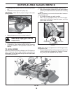
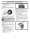
BELT INSTALLATION -
• Install new belt from tractor rear to front, over the steer-
ing plate (H) and above clutch brake pedal shaft (J).
• Pull belt toward front of tractor and roll belt around
electric clutch and onto engine pulley (G).
• Pull belt toward rear of tractor. Carefully work belt down
around transmission cooling fan and onto the input
pulley (F). Be sure belt is inside the belt keeper.
• Install belt on centerspan idler (E).
• Install belt through stationary idler (C) and clutch ing
idler (D).
M
K
L
Q
S
P
R
R
Q
P
R
electric
02953
A
B
C
D
E
F
G
H
J
FIG. 28
CAUTION: Belt tension rod is spring
loaded. Have a tight grip on rod and
engage slowly.
• Raise attachment lift lever to highest position.
• Reinstall anti-rotation link (B) on right side of tractor.
Tighten securely.
• Reconnect clutch harness (A).
• Make sure belt is in all pulley grooves and in side all
belt guides and keep ers.
• Install mower (See “TO IN STALL MOWER” in this sec-
tion of manual).
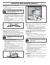
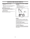
TO REMOVE WHEEL FOR REPAIRS
(See Fig. 31)
• Block up axle securely.
• Remove axle cover, retaining ring and washers to allow
wheel removal (rear wheel contains a square key - Do
not lose).
FRONT WHEEL TOE-IN/CAM BER
Your new tractor front wheel toe-in and camber is set at the
factory and is normal. The front wheel toe-in and camber
are not adjustable. If damage has occurred to affect the
factory set front wheel toe-in or camber, contact a qualifi ed
service center.
TO CHECK BRAKE
If tractor requires more than fi ve (5) feet to stop at highest
speed in high est gear on a level, dry concrete or paved
surface, then brake must be serviced.
You may also check brake by:
• Park tractor on a level, dry concrete or paved surface,
depress brake pedal all the way down and engage
parking brake.
• Disengage transmission by placing freewheel control
in “transmission disengaged” position. Pull freewheel
control out and into the slot and release so it is held in
the disengaged position.
The rear wheels must lock and skid when you try to manu-
ally push the tractor forward. If the rear wheels rotate, then
the brake needs to be serviced. Contact a qualifi ed service
center.