


18
SERVICE AND ADJUSTMENTS
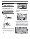
CAUTION: After rear lift links are dis-
connected, the attachment lift lever will
be spring loaded. Have a tight grip on
lift lever when changing position of
the lever.
• Turn tractor steering wheel to the left as far as it will
go.
• Slide mower out from under right side of tractor.
• Turn steering wheel to position wheels straight for-
ward.
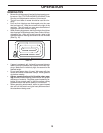
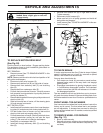
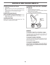
• ATTACH FRONT LINK (E) - Work from left side of trac-
tor. Insert rod end of link assembly through front hole
in tractor front suspension bracket (F) and secure with
retainer spring (G) through hole in link located behind
the bracket.
• Insert other end of link (E) into hole in front mower bracket
(H) and secure with washer and retainer spring (J).
A
B
C
D
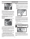
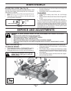
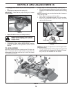
TO INSTALL MOWER (See Figs. 18-22)
Be sure tractor is on level surface and engage park ing
brake.
• Lower attachment lift lever to it's lowest position.
CAUTION: Lift lever is spring loaded.
Have a tight grip on lift lever, lower it
slowly and engage in lowest position.
• Turn steering wheel to the left as far as it will go and
position mower on right side of tractor with defl ector
shield to the right.
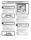
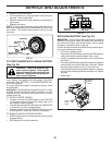
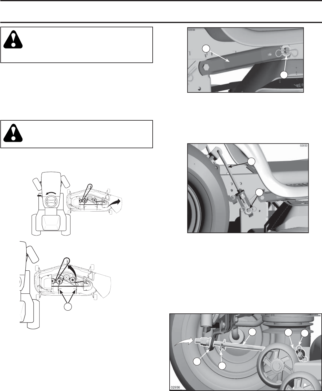
• ATTACH REAR LIFT LINKS (C) - Lift rear corner of
mower and position slot in link assembly over pin on
rear mower bracket (D) and secure with washer and
retainer spring.
• Repeat on opposite side of tractor.
NOTE: Be sure mower side suspension arms (A) are pointing
forward before sliding mower under tractor.
• Slide mower under tractor until it is centered under
tractor.
• ATTACH MOWER SIDE SUSPENSION ARMS (A) TO
CHASSIS - Position hole in arm over pin (B) on outside
of tractor chassis and secure with washer and retainer
spring.
• Repeat on opposite side of tractor.
02965
0
2
0
5
1
A
FIG. 18
FIG. 19
02965
E
F
H
G
J
FIG. 20