


ASSEMBLY
7
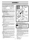
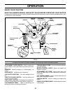
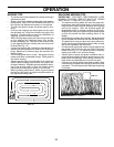
DISCARD TERMINAL
PROTECTIVE CAPS
LOCK
WASHER
HEX NUT
TERMINAL
ACCESS
DOOR
POSITIVE
(RED) CABLE
NEGATIVE
(BLACK) CABLE
FLAT
WASHER
HEX
BOLT
FIG. 2
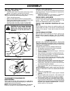
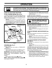
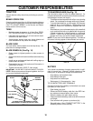
INSTALL SEAT (See Fig. 3)
Adjust seat before tightening adjustment knob.
• Remove cardboard packing on seat pan.
• Place seat on seat pan and assemble shoulder bolt.
• Assemble adjustment knob and flat washer loosely.
Do not tighten.
• Tighten shoulder bolt securely.
• Lower seat into operating position and sit on seat.
• Slide seat until a comfortable position is reached which
allows you to press clutch/brake pedal all the way
down.
• Get off seat without moving its adjusted position.
• Raise seat and tighten adjustment knob securely.
SEAT PAN
SEAT
SHOULDER
BOLT
ADJUSTMENT
KNOB
LARGE FLAT WASHER
FIG. 3
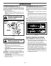
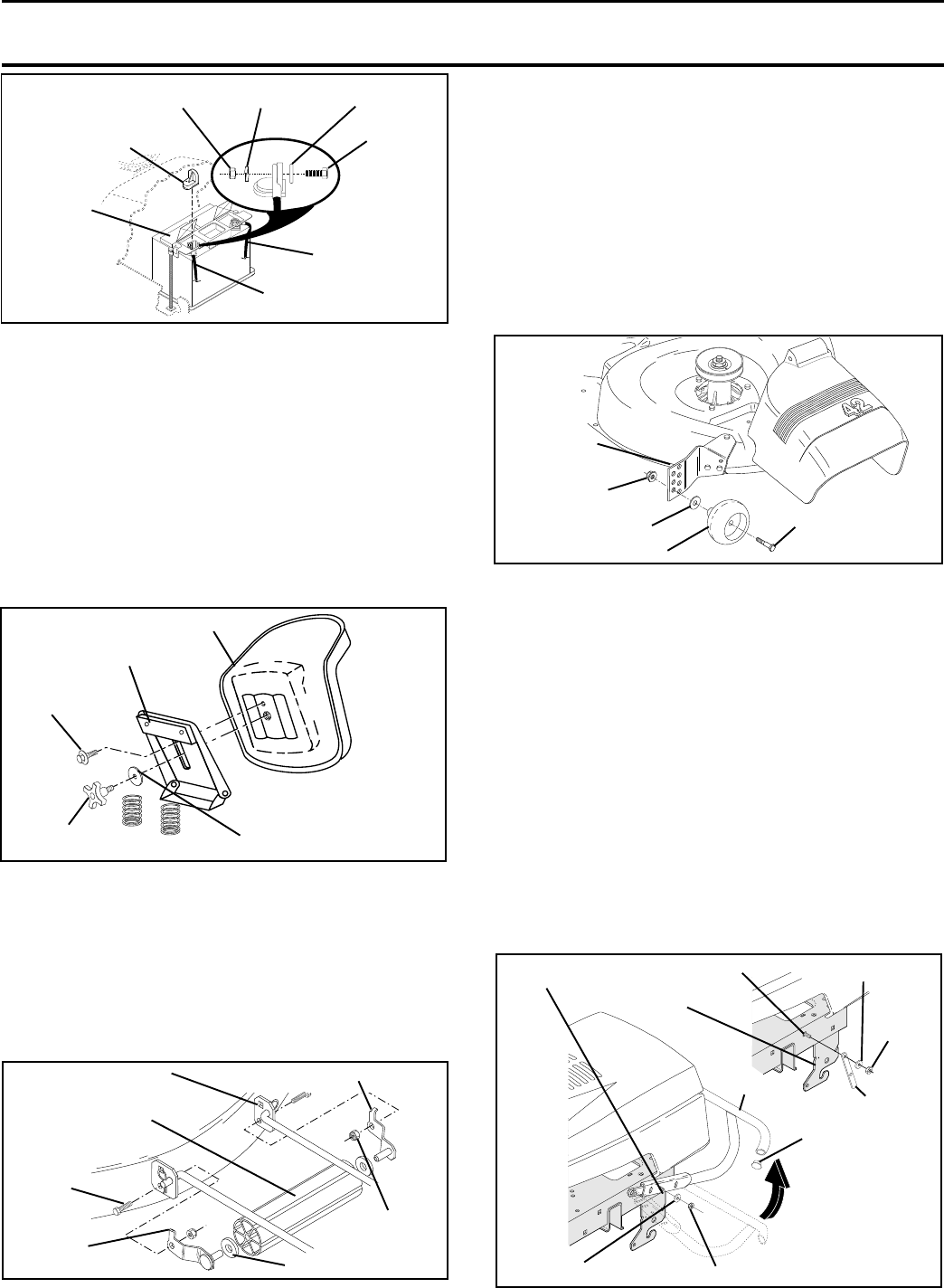
TO ATTACH NOSE ROLLER (See Fig. 4)
• Position brackets, 17/32 x 7/8 x 16 gauge washers, and
nose roller between deck mounting brackets as shown.
Be sure to position brackets on correct side, as shown.
• Install 3/8-16 x 1 hex bolts and 3/8-16 crownlock nuts
as shown. Tighten hardware securely.
NOTE: Be sure bracket tabs are positioned in tab holes in
deck brackets.
NOSE ROLLER
HEX
BOLT
“B”
BRACKET
TAB
TAB HOLE
CROWNLOCK
NUT
“A” BRACKET TAB
WASHER
FIG. 4
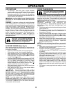
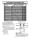
ASSEMBLE GAUGE WHEELS TO MOWER
DECK (See Fig. 5)
Assemble gauge wheels with tractor on a flat level surface.
• Adjust mower to desired cutting height (See “TO AD-
JUST MOWER CUTTING HEIGHT” in the Operation
section of this manual).
• With mower in desired height of cut position, gauge
wheels should be assembled so they are slightly off the
ground. Install gauge wheel in appropriate hole with
shoulder bolt, 3/8 washer, and 3/8-16 locknut and
tighten securely.
• Repeat for opposite side installing gauge wheel in
same adjustment hole.
GAUGE
WHEEL
MOUNTING
BRACKET
3/8 WASHER
3/8-16
LOCKNUT
GAUGE WHEEL
SHOULDER BOLT
FIG. 5
TO ATTACH FRONT BUMPER (See Fig. 6)
NOTE: For ease of assembly, you may wish to obtain the
assistance of another person for mounting bumper to
tractor.
• Press or tap the end caps into ends of bumper tube.
• On both sides of chassis, position extension bracket as
shown and loosely assemble to rear chassis hole with
supplied 3/8-16 x 1-1/4 carriage bolt, 13/32 washer and
3/8-16 crownlock nut from parts bag. Do not tighten the
brackets. Allow them to hang from the chassis.
• Position bumper and extension brackets so brackets
can be slid inside flattened ends of bumper.
• Slide bumper onto brackets and pivot upwards to align
center hole in bumper with holes in extension brackets
and tractor chassis.
• With all holes aligned, assemble carriage bolt, washer,
and locknut to both sides of tractor chassis.
• Tighten all four (4) locknuts securely.
CARRIAGE
BOLT
FIG. 6
WASHER
LOCKNUT
END CAP
Slide Onto Extension
Brackets And Pivot
Upwards
BUMPER
FRONT
SUSPENSION
BRACKET
EXTENSION
BRACKET
LOCKNUT
WASHER
CARRIAGE BOLT