


ASSEMBLY
6
Your new tractor has been assembled at the factory with exception of those parts left unassembled for shipping purposes.
To ensure safe and proper operation of your tractor all parts and hardware you assemble must be tightened securely. Use
the correct tools as necessary to insure proper tightness.
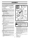
TOOLS REQUIRED FOR ASSEMBLY
A socket wrench set will make assembly easier. Standard
wrench sizes are listed.
(2) 7/16" wrenches Phillips Screwdriver
(1) 1/2" wrench Tire pressure gauge
(2) 9/16" wrenches Utility knife
(1) 3/4" socket with drive rachet
When right or left hand is mentioned in this manual, it
means when you are in the operating position (seated
behind the steering wheel).
TO REMOVE TRACTOR FROM CARTON
UNPACK CARTON
• Remove all accessible loose parts and parts cartons
from carton (See page 5).
• Cut, from top to bottom, along lines on all four corners
of carton, and lay panels flat.
• Check for any additional loose parts or cartons and
remove.
BEFORE ROLLING TRACTOR OFF SKID
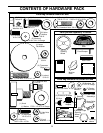
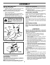
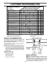
ATTACH STEERING WHEEL (See Fig. 1)
PREASSEMBLE SLEEVE TO STEERING WHEEL (See
Fig. 1 Inset)
• Install sleeve retainer clips, evenly spaced around
steering wheel hub, with formed tabs toward the out-
side of hub.
• Press or lightly tap retainer clips fully onto steering
wheel hub.
• Press steering sleeve fully onto steering wheel hub and
clips.
ASSEMBLE EXTENSION SHAFT
• Slide extension shaft onto lower steering shaft. Align
mounting holes in extention and lower shafts and
install 5/16 hex bolt and locknut. Tighten securely.
IMPORTANT: TIGHTEN BOLT AND NUT SECURELY TO
18-22 FT. LBS TORQUE.
INSTALL STEERING WHEEL
• Position front wheels of the tractor so they are pointing
straight forward.
• Slide steering wheel adapter onto steering shaft exten-
sion.
• Position steering wheel and sleeve assembly so cross
bars are horizontal (left to right) and slide onto adapter.
• Assemble large flat washer and 3/8-24 locknut and
tighten securely.
• Snap steering wheel insert into center of steering
wheel.
• Remove protective plastic from tractor hood and grill.
IMPORTANT: CHECK FOR AND REMOVE ANY STAPLES
IN SKID THAT MAY PUNCTURE TIRES WHERE TRACTOR
IS TO ROLL OFF SKID.
TO ROLL TRACTOR OFF SKID (See Fig. 8)
• Release parking brake by depressing clutch/brake
pedal.
• Place freewheel control in freewheeling position to
disengage transmission (See “TO TRANSPORT” in
the Operation section of this manual).
• Roll tractor backwards off skid.
• Remove banding holding discharge guard up against
tractor.
STEERING
SLEEVE
INSERT
3/8-24 LOCKNUT
LARGE FLAT
WASHER
STEERING
WHEEL
RETAINER CLIPS
(TAB TO OUTSIDE)
STEERING
WHEEL HUB
STEERING
SLEEVE
ADAPTER
EXTENSION SHAFT
5/16 HEX BOLT
5/16 LOCKNUT
LOWER
STEERING
SHAFT
FIG. 1
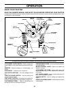
CONNECT BATTERY (See Fig. 2)
CAUTION: Do not short battery termi-
nals. Before connecting battery, re-
move metal bracelets, wristwatch
bands, rings, etc.
Positive terminal must be connected
first to prevent sparking from acciden-
tal grounding.
• Lift hood to raised position.
• Open terminal access doors, remove terminal protec-
tive caps and discard.
• If this battery is put into service after month and year
indicated on label (label located between terminals)
charge battery for minimum of one hour at 6-10 amps.
• First connect RED battery cable to positive (+) battery
terminal with hex bolt, flat washer, lock washer and hex
nut as shown. Tighten securely.
• Connect BLACK grounding cable to negative (-) battery
terminal with remaining hex bolt, flat washer, lock
washer and hex nut. Tighten securely.
• Close terminal access doors.
Use terminal access doors for:
• Inspection for secure connections (to tighten hard-
ware).
• Inspection for corrosion.
• Testing battery.
• Jumping (if required).
• Periodic charging.