


ASSEMBLY
7
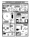
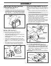
FIG. 3
FIG. 2
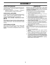
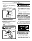
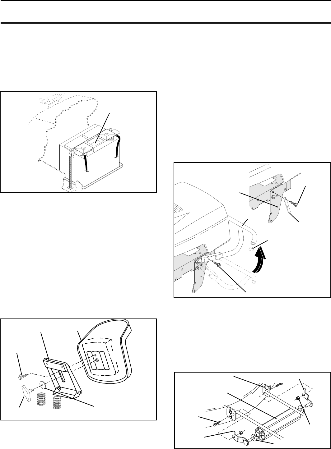
TO ATTACH NOSE ROLLER (See Fig. 5)
• Position brackets, 17/32 x 7/8 x 16 gauge washers, and
nose roller between deck mounting brackets as shown.
Be sure to position brackets on correct side, as shown.
• Install 3/8-16 x 1 hex bolts and 3/8-16 lock nuts as
shown. Tighten hardware securely.
NOTE: Be sure bracket tabs are positioned in tab holes in
deck brackets.
NOSE ROLLER
HEX
BOLT
“B”
BRACKET
TAB
TAB HOLE
LOCK NUT
“A” BRACKET TAB
WASHER
FIG. 5
HOW TO SET UP YOUR TRACTOR
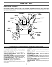
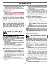
CHECK BATTERY (See Fig. 2)
• Lift hood to raised position.
• If this battery is put into service after month and year
indicated on label (label located between terminals)
charge battery for minimum of one hour at 6-10 amps.
(See «BATTERY» in CUSTOMER RESPONSIBILI-
TIES section of this manual for charging instructions).
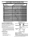
SEAT PAN
SHOULDER
BOLT
ADJUSTMENT
KNOB
FLAT WASHER
SEAT
INSTALL SEAT (See Fig. 3)
Adjust seat before tightening adjustment knob.
• Remove cardboard packing on seat pan.
• Place seat on seat pan and assemble shoulder bolt.
Tighten shoulder bolt securely.
• Assemble adjustment knob and flat washer loosely.
Do not tighten.
• Lower seat into operating position and sit on seat.
• Slide seat until a comfortable position is reached which
allows you to press clutch/brake pedal all the way
down.
• Get off seat without moving its adjusted position.
• Raise seat and tighten adjustment knob securely.
LABEL
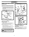
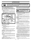
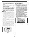
TO ATTACH FRONT BUMPER (See Fig. 4)
NOTE: For ease of assembly, you may wish to obtain the
assistance of another person for mounting bumper to
tractor.
• Press or tap the end caps into ends of bumper tube.
• The existing top screw and the existing front screw
must be removed from both sides.
• On both sides of chassis, position extension bracket as
shown and loosely assemble to rear chassis hole with
supplied 3/8-16 x 1-1/4 bolt. Do not tighten the brack-
ets. Allow them to hang from the chassis.
• Position bumper and extension brackets so brackets
can be slid inside flattened ends of bumper.
• Slide bumper onto brackets and pivot upwards to align
center holes in extension brackets and tractor chassis.
• With holes aligned, install additional screws.
• Tighten all four (4) bolts securely.
Slide Bumper onto
Extension Brackets
and Pivot Upwards
FRONT BOLT
BUMPER
FRONT
SUSPENSION
BRACKET
EXTENSION
BRACKET
TOP BOLT
FIG. 4
END CAP