


18
SERVICE AND ADJUSTMENTS
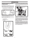
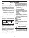
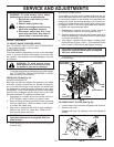
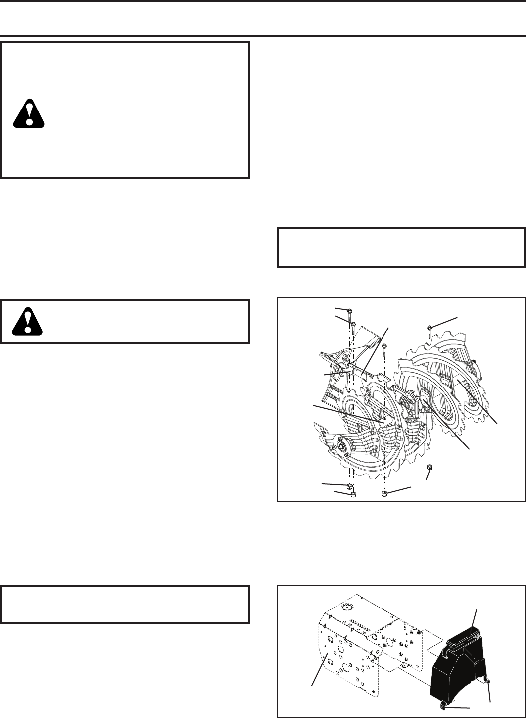
SHEAR BOLTS (See Fig. 25)
AUGER SHEAR BOLTS
Both right and left-hand augers are secured to the auger
shaft with a shear bolt and hex nut. Should a foreign ob-
ject or ice become lodged in the augers, the shear bolts
are designed to break, preventing damage to any other
com po nents. If one or both augers do not turn when auger
control lever is engaged, check to see if one or both of the
bolts have sheared. To replace the shear bolts:
1. Disengage all controls and move throttle control to
STOP position. Wait for all moving parts to stop.
2. Remove safety ignition key and disconnect spark plug
wire from spark plug. Place wire where it cannot come
in contact with spark plug.
3. Align hole in auger hub with hole in auger shaft and
install a new 1/4-20 x 2" shear bolt. Install 1/4-20
lock nut and tighten securely.
CAUTION: Do not sub sti tute. Use only original
equip ment shear bolts as sup plied with your
snow thrower.
4. Insert safety ignition key and reconnect spark plug wire
to spark plug.
CHUTE DEFLECTOR
The chute deflector, attached to the top of the discharge
chute, is provided to direct discharging snow away from
the operator. If the deflector becomes damaged, it should
be re placed.
WARNING: To avoid serious injury,
nev er operate your snow thrower with
the deflector removed or damaged.
• To change direction and/or distance snow is dis charged,
see “TO CONTROL SNOW DISCHARGE” in the Op-
er a tion section of this manual.
IMPELLER SHEAR BOLTS
The impeller is secured to the impeller shaft with two (2)
capscrew/shear bolts and hex nuts. Should a foreign object
or ice become lodged in the impeller, the capscrews are
de signed to break, preventing damage to any other com-
po nents. If impeller does not turn when auger control lever
is engaged, check to see if the capscrews have sheared.
To replace the capscrew/shear bolts:
1. Disengage all controls and move throttle control to
STOP position. Wait for all moving parts to stop.
2. Remove safety ignition key and disconnect spark plug
wire from spark plug. Place wire where it cannot come
in contact with spark plug.
3. Align holes in impeller hub with holes in impeller shaft
and install two (2) new 1/4-20 x 1-5/8" capscrew/shear
bolts. Install 1/4-20 locknuts and tighten securely.
CAUTION: Do not substitute. Use only original
equip ment capscrew/shear bolts as sup plied
with your snow thrower.
4. Insert safety ignition key and reconnect spark plug wire
to spark plug.
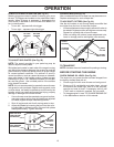
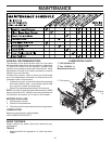
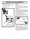
TO REMOVE BELT COVER (See Fig. 26)
1. Loosen the two (2) screws securing belt cover to frame.
2. Remove belt cover.
• Replace belt cover by installing cover and tightening
screws.
BELT
COVER
SCREWS
FRAME
FIG. 26
WARNING: To avoid serious injury, before
performing any service or ad just ments:
1. Be sure the on/off switch is in the
OFF position.
2. Remove safety ignition key.
3. Make sure the augers and all mov ing
parts have completely stopped.
4. Disconnect spark plug wire from
spark plug and place wire where it
can not come in contact with plug.
SNOW THROWER
TO ADJUST SNOW THROWER HEIGHT
See “TO ADJUST SKID PLATES” and “SCRAPER BAR”
in the Operation section of this manual.
FIG. 25
AUGER SHAFT
SHOULDER /
SHEAR BOLT
SHOULDER /
SHEAR BOLT
1/4-20
LOCK NUT
1/4-20
LOCK NUT
IMPELLER
SHAFT
IMPELLER
HUB
AUGER
HUB
AUGER
HUB