


20
SERVICE AND ADJUSTMENTS
01268
"D"
"D"
MANDREL
FIG. 18
FIG.19
BOTH FRONT LINKS MUST BE EQUAL IN LENGTH
01267
SUSPENSION ARM
01553
LIFT LINK ADJUSTMENT NUT
FIG. 17
0
1
1
5
6
NUT "E"
NUT "F"
FRONT LINKS
TRUN NION
00598
FIG. 16
“A”
“A”
BOTTOM EDGE OF
MOWER
TO GROUND
BOTTOM EDGE
OF MOWER
TO GROUND
GROUND LINE
TO LEVEL MOWER HOUSING
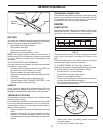
Adjust the mower while tractor is parked on level ground
or driveway. Make sure tires are properly inflated (See
“PROD UCT SPECIFICATIONS” section of this manual). If
tires are over or underinflated, you will not properly adjust
your mower.
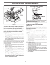
SIDE-TO-SIDE ADJUSTMENT (See Figs. 16 and 17)
• Raise mower to its highest position.
• At the midpoint of both sides of mower, measure height
from bot tom edge of mower to ground. Distance “A”
on both sides of mower should be the same or within
1/4" of each other.
• If adjustment is necessary, make adjustment on one
side of mower only.
• To raise one side of mower, tighten lift link ad just ment
nut on that side.
• To lower one side of mower, loosen lift link ad just ment
nut on that side.
NOTE: Three full turns of adjustment nut will change mower
height about 1/8".
• Recheck measurements after adjusting.
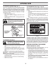
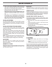
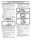
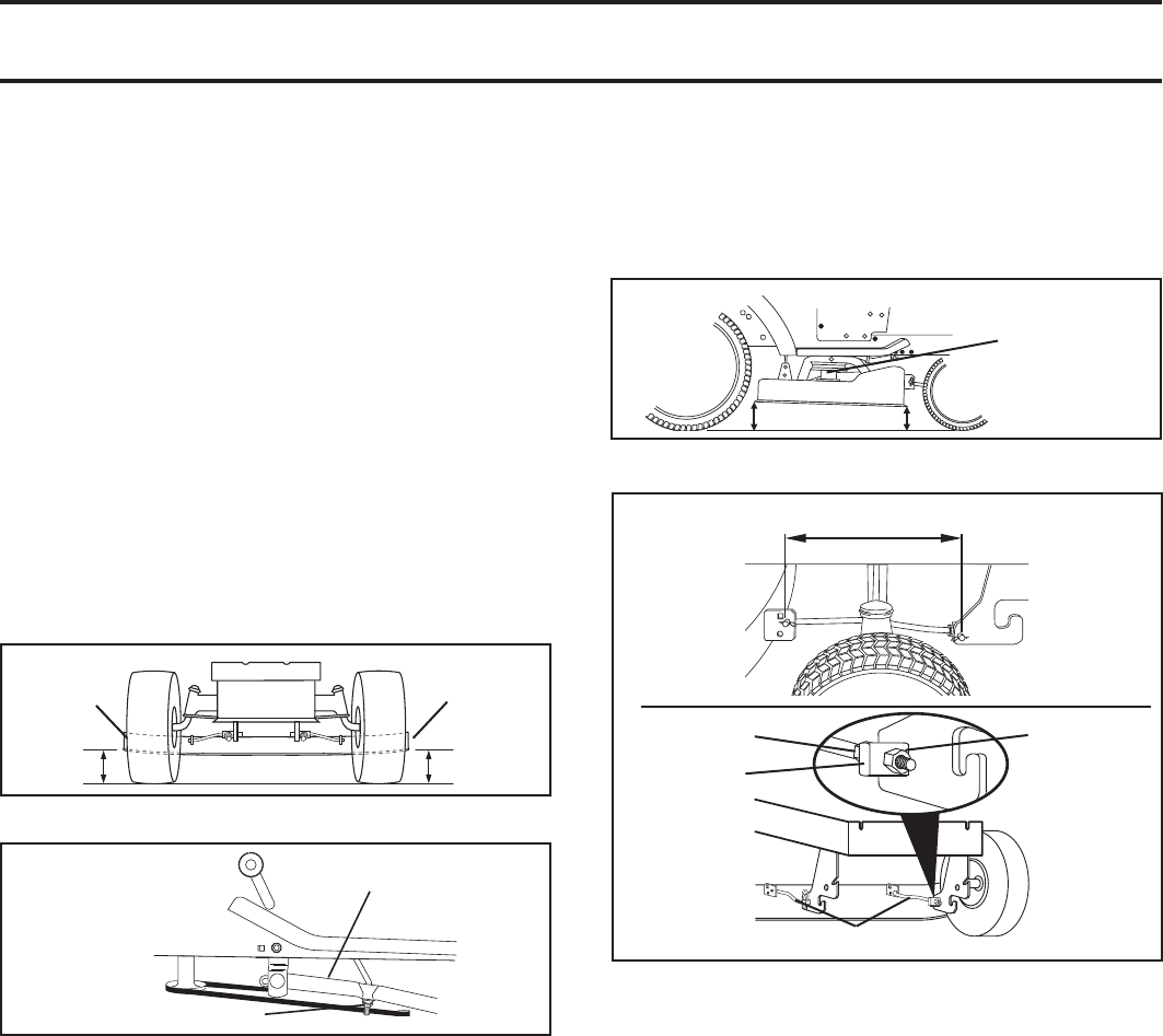
FRONT-TO-BACK ADJUSTMENT (See Figs. 18 and 19)
IMPORTANT: DECK MUST BE LEVEL SIDE-TO-SIDE. IF THE
FOLLOWING FRONT-TO-BACK ADJUSTMENT IS NECESSARY,
BE SURE TO AD JUST BOTH FRONT LINKS EQUAL LY SO
MOWER WILL STAY LEVEL SIDE-TO-SIDE.
To obtain the best cutting results, the mower housing
should be adjusted so that the front is approximately 1/8"
to 1/2" lower than the rear when the mower is in its high-
est position.
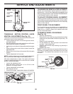
Check adjustment on right side of tractor. Measure dis tance
“D” directly in front and behind the mandrel at bottom edge
of mower housing as shown.
• Before making any necessary adjustments, check that
both front links are equal in length.
• If links are not equal in length, adjust one link to same
length as other link.
• To lower front of mower loosen nut “E” on both front
links an equal number of turns.
• When distance “D” is 1/8" to 1/2" lower at front than rear,
tighten nuts “F” against trunnion on both front links.
• To raise front of mower, loosen nut “F” from trunnion
on both front links. Tighten nut “E” on both front links
an equal number of turns. The two front links must
remain equal in length.
• When distance “D” is 1/8" to 1/2" lower at front than rear,
tighten nut “F” against trunnion on both front links.
• Recheck side-to-side adjustment.
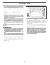
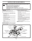
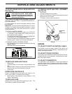
TO REPLACE MOWER BLADE DRIVE BELT
(See Fig. 20)
The mower blade drive belt may be replaced without tools.
Park the tractor on level surface. Engage parking brake.
BELT REMOVAL -
• Place attachment clutch in “DISENGAGED” po si tion.
• Move at tach ment lift lever forward to lower mower to
its lowest position.
• Roll belt off engine pulley.
• Work belt off both mandrel pulleys and idler pulleys.
• Pull belt away from mower.
BELT INSTALLATION -
• Work new belt around both mandrel pulleys and idler
pulleys.
• Install new belt into engine pulley groove.
• Make sure belt is inside the belt keeper at the idler and
on both sides of the wire belt keeper as shown.
IMPORTANT: CHECK BELT FOR PROPER ROUTING IN ALL
MOWER PULLEY GROOVES.