


21
02548
B
B
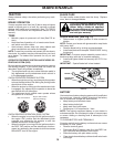
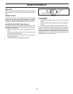
NOTE: Each full turn of the adjustment nut will change
mower height about 1/8".
• Recheck measurements, adjust if necessary until front
tip of blade is 1/8" to 1/2" lower than the rear tip.
• Hold adjustment nut in position with wrench and tighten
jam nut securely against adjustment nut.
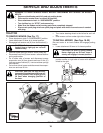
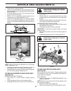
• Raise mower to highest position.
• Position any blade so the tip is pointing straight forward.
Measure distance (B) to the ground at front and rear
tip of the blade.
• If front tip of blade is not 1/8" to 1/2" lower than the rear
tip, go to the front of tractor.
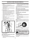
• With an 11/16" or adjustable wrench, loosen jam nut
A several turns to clear adjustment nut B.
• With a 3/4" or adjustable wrench, turn front link adjust-
ment nut (B) clockwise (ltighten) to raise the front of
mower, or, counterclockwise (loosen) to lower the front
mower.
B
02950
Tighten adjust nut
B to raise mower
Loosen adjust nut
B to lower mower
Loosen jam nut A fi rst
A
FIG. 26
SERVICE AND ADJUSTMENTS
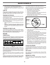
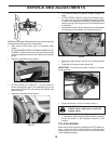
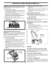
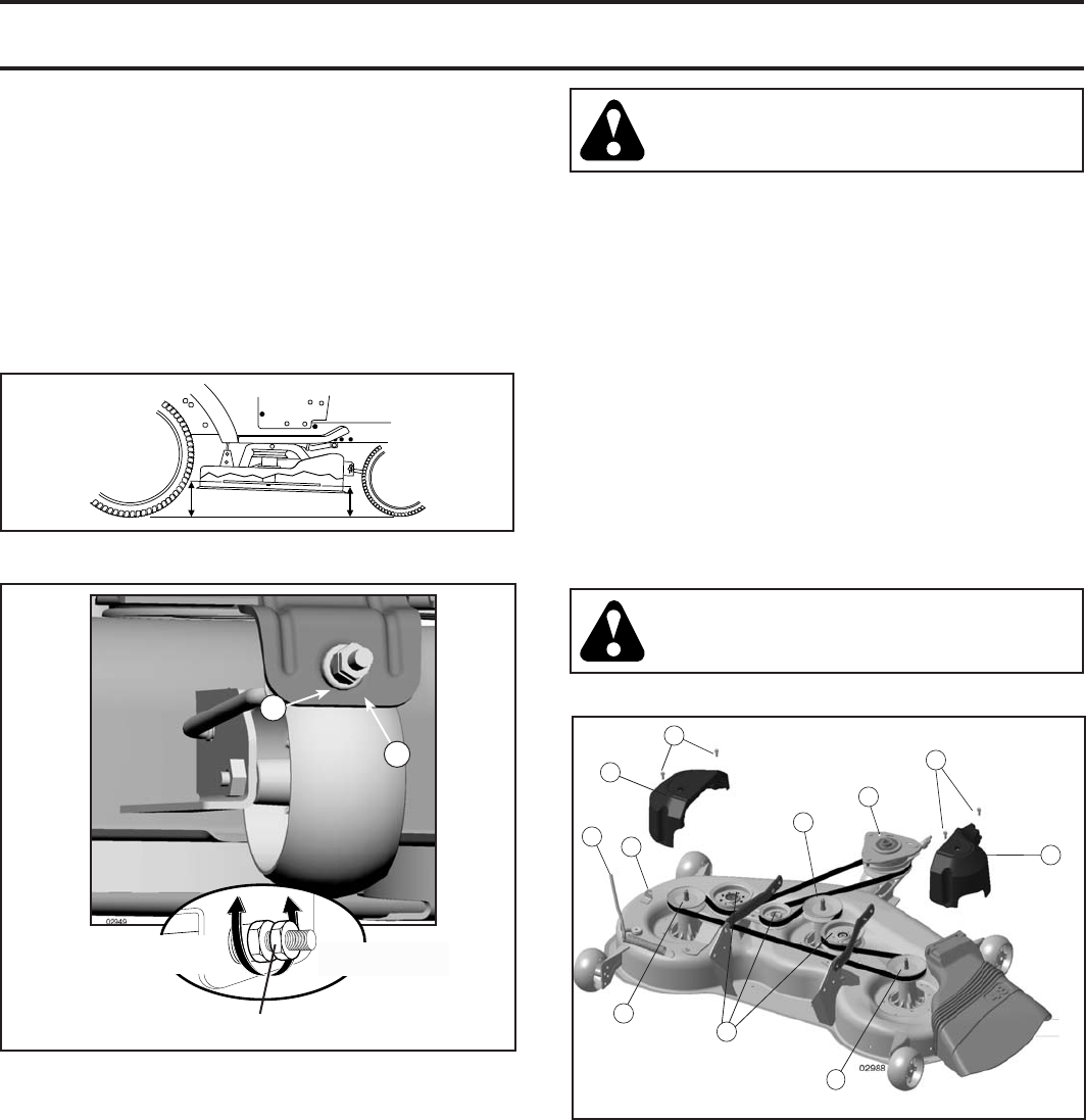
TO REPLACE MOWER BLADE DRIVE BELT
(See Fig. 27)
MOWER DRIVE BELT REMOVAL
• Park tractor on a level surface. En gage parking
brake.
• Lower attachment lift lever to its lowest position.
• Disengage belt tension rod (K) from lock bracket (L).
FIG. 25
CAUTION: Belt tension rod is spring
loaded. Have a fi rm grip on rod and
release slowly.
• Remove screws (P) from mandrel covers (Q) and re-
move covers.
• Remove any dirt or grass clippings which may have
accumulated around mandrels and entire upper deck
surface.
• Remove belt from electric clutch pulley (M), both man-
drel pulleys (R) and all idler pulleys (S).
MOWER DRIVE BELT INSTALLATION
• Install belt around all mandrel pulleys (R) and around
idler pulleys (S) as shown.
• Install belt onto electric clutch pulley (M).
IMPORTANT: Check belt for proper routing in all mower
pulley grooves.
• Reassemble mandrel covers (Q). Securely tighten all
screws.
• Engage belt tension rod (K) on locking bracket (L).
CAUTION: Belt tension rod is spring
loaded. Have a tight grip on rod and
engage slowly.
• Raise attachment lift lever to highest position.
FIG. 27
M
K
L
Q
S
P
R
R
Q
P
R
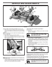
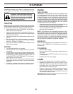
TO REPLACE MOTION DRIVE BELT
(See Fig. 28)
Park the tractor on level surface. En gage parking brake.
For as sis tance, there is a belt installation guide decal on
bottom side of left footrest.
BELT REMOVAL -
• Remove mower (See “TO RE MOVE MOWER” in this
section of manual).
NOTE: Observe entire motion drive belt and position of all
belt guides and keepers.
• Disconnect clutch wire harness (A).
• Remove anti-rotation link (B) on right side of tractor.