


19
SERVICE AND ADJUSTMENTS
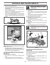
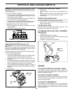
• Turn steering wheel to position wheels straight for-
ward.
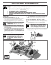
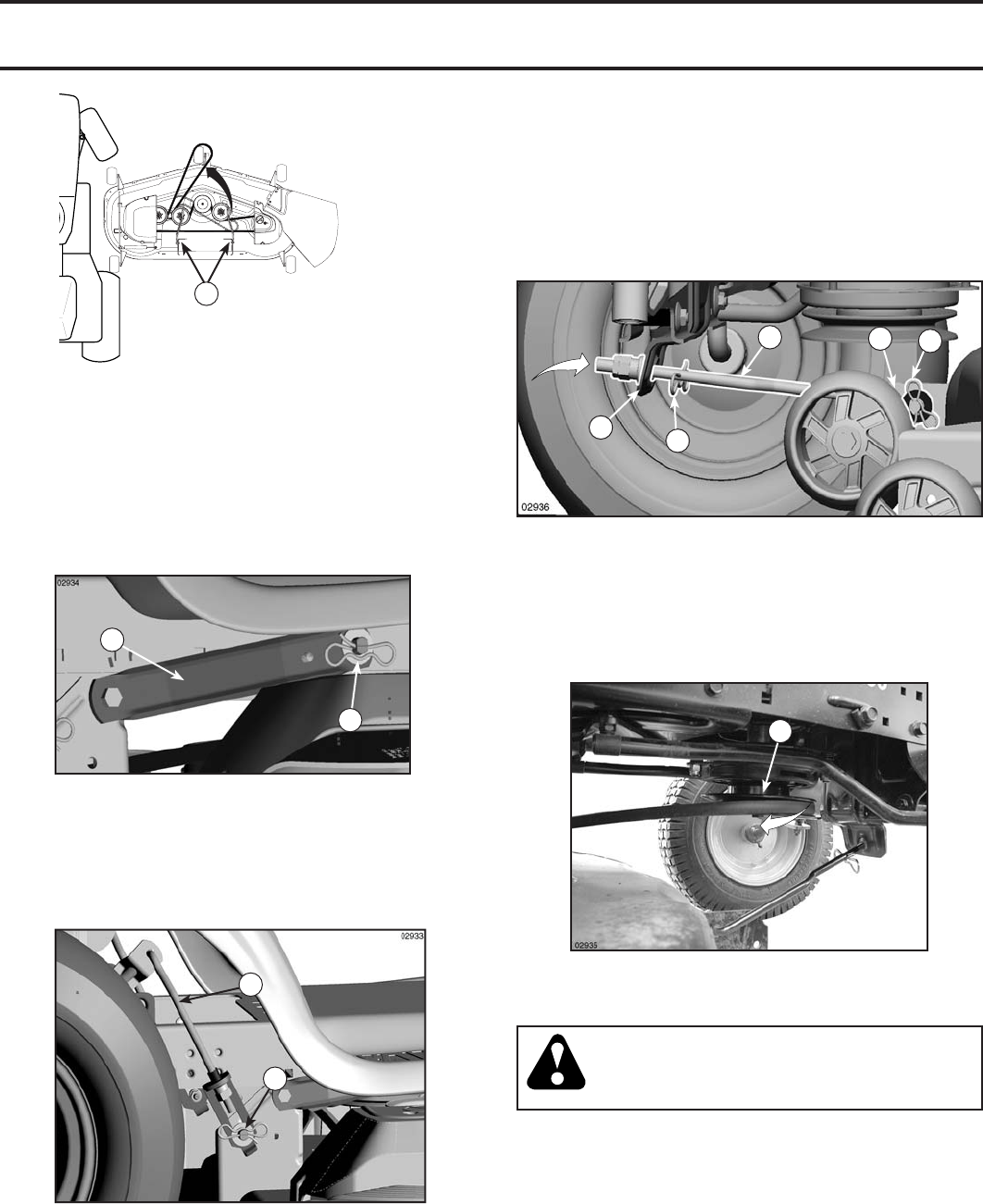
• ATTACH FRONT LINK (E) - Work from left side of trac-
tor. Insert rod end of link assembly through front hole
in tractor front suspension bracket (F) and secure with
retainer spring (G) through hole in link located behind
the bracket.
• Insert other end of link (E) into hole in front mower bracket
(H) and secure with washer and retainer spring (J).
A
B
C
D
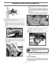
• ATTACH REAR LIFT LINKS (C) - Lift rear corner of
mower and position slot in link assembly over pin on
rear mower bracket (D) and secure with washer and
retainer spring.
• Repeat on opposite side of tractor.
NOTE: Be sure mower side suspension arms (A) are pointing
forward before sliding mower under tractor.
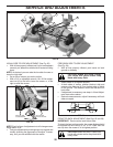
• Slide mower under tractor until it is centered under
tractor.
• ATTACH MOWER SIDE SUSPENSION ARMS (A) TO
CHASSIS - Position hole in arm over pin (B) on outside
of tractor chassis and secure with washer and retainer
spring.
• Repeat on opposite side of tractor.
02965
020
5
1
A
FIG. 18
FIG. 19
E
F
H
G
J
FIG. 20
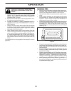
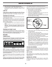
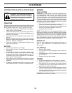
TO LEVEL MOWER
Make sure tires are properly infl ated to the PSI shown on
tires. If tires are over or under infl ated, it may affect the
appearance of your lawn and lead you to think the mower
is not adjusted properly.
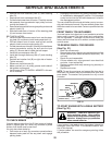
• Disengage belt tension rod (K) from locking bracket
(L).
• Install belt onto engine clutch pulley (M).
IMPORTANT: Check belt for proper routing in all mower
pulley grooves.
M
• Engage belt tension rod (K) on locking bracket (L).
CAUTION: Belt tension rod is spring
loaded. Have a tight grip on rod and
engage slowly.
• Raise attachment lift lever to highest position.
• If necessary, adjust gauge wheels before op er at ing
mower as shown in the Operation section of this
manual.
FIG. 21