


8
ASSEMBLY
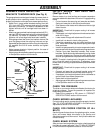
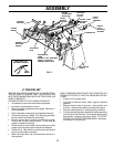
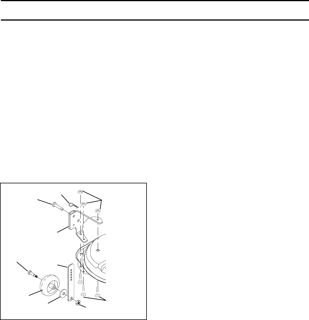
FIG. 5
ASSEMBLE GAUGE WHEELS AND
BRACKETS TO MOWER DECK (See Fig. 5)
The gauge wheels are designed to keep the mower deck in
proper position when operating mower. Be sure they are
properly adjusted to ensure optimum mower performance.
• Attach front gauge wheel brackets marked front left
(FL), front right (FR) to mower deck using (3) carriage
bolts and (3) locknuts. For ease of installation do not
tighten locknuts until all carriage bolts have been in-
stalled.
• Attach rear gauge wheel brackets marked rear left (R L),
rear right (RR) to mower deck using (3) carriage bolts and
(3) locknuts. For ease of installation do not tighten
locknuts until all carriage bolts have been installed.
• Slide gauge wheel bar down into bracket channel, Be
sure that gauge wheel bar aligning holes are on top.
Assemble gauge wheels as shown using shoulder bolts,
3/8 washers and 3/8-16 center locknuts and tighten
securely.
• Adjust gauge wheels to highest position for ease of
mower deck assembly.
• Adjust gauge wheels before operating mower as shown
in the operation section of this manual.
SHOULDER
BOLT
GAUGE
WHEEL
3/8-16 CENTER
LOCKNUT
GAUGE
WHEEL
MOUNTING
BRACKET
3/8 WASHER
CARRIAGE
BOLTS
CROWNLOCK
NUT
ADJUSTING
BAR
PIN
RETAINER
SPRING
INSTALL MOWER AND DRIVE BELT
(See Figs. 6 and 7)
Be sure tractor is on level surface and mower suspension
arms are raised with attachment lift control. Engage parking
brake.
• Cut and remove ties securing anti-sway bar and belts.
Swing anti-sway bar to left side of mower deck.
• Slide mower under tractor with deflector shield to right
side of tractor.
IMPORTANT: Check belt for proper routing in all mower
pulley grooves.
• If equipped, turn height adjustment knob counterclock-
wise until it stops.
• Lower mower linkage with attachment lift control.
• Install belt into electric clutch pulley groove.
• Place the suspension arms on inward pointing deck
pins. Retain with double loop retainer spring with loops
down as shown.
• Install front plate assembly to tractor suspension brack-
ets and retain with single loop retainer springs as shown.
• Position front plate assembly between front mower
brackets. Raise deck and plate assembly to align holes
and insert flanged pins. Secure pins with double loop
retainer springs between the plate and mower brackets.
NOTE: To assist in locating hole in flanged pin, the hole in
pin is inline with notch on head of pin. If necessary, move
mower side-to-side to give space between plate and mower
brackets.
IMPORTANT: Check belt for proper routing in all mower
pulley grooves.
• Connect anti-sway bar to chassis bracket under left
footrest and retain with double loop retainer spring.
• If equipped, turn height adjustment knob clockwise to
remove slack from mower suspension.
• Raise deck to highest position.
• Adjust gauge wheels before operating mower as shown
in the Operation section of this manual.
CHECK TIRE PRESSURE
The tires on your tractor were overinflated at the factory for
shipping purposes. Correct tire pressure is important for
best cutting performance.
• Reduce tire pressure to PSI shown in “PRODUCT
SPECIFICATIONS” section of this manual.
CHECK MOWER LEVELNESS
For best cutting results, mower should be properly leveled.
See “TO LEVEL MOWER HOUSING” in the Service and
Adjustments section of this manual.
CHECK FOR PROPER POSITION OF ALL
BELTS
See the figures that are shown for replacing motion, mower
drive, and mower blade drive belts in the Service and
Adjustments section of this manual. Verify that the belts are
routed correctly.
CHECK BRAKE SYSTEM
After you learn how to operate your tractor, check to see that
the brake is properly adjusted. See “TO ADJUST BRAKE”
in the Service and Adjustments section of this manual.