


20
SERVICE AND ADJUSTMENTS
CAUTION: BEFORE PERFORMING ANY SERVICE OR ADJUSTMENTS:
• Depress clutch/brake pedal fully and set parking brake.
• Place motion control lever in neutral (N) position.
• Place attachment clutch in “DISENGAGED” position.
• Turn ignition key “OFF” and remove key.
• Make sure the blades and all moving parts have completely stopped.
• Disconnect spark plug wire from spark plug and place wire where it cannot come in contact with
plug.
TO LEVEL MOWER HOUSING
Adjust the mower while tractor is parked on level ground or
driveway. Make sure tires are properly inflated (See “PROD-
UCT SPECIFICATIONS” section of this manual). If tires are
over or underinflated, you will not properly adjust your
mower.
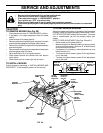
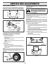
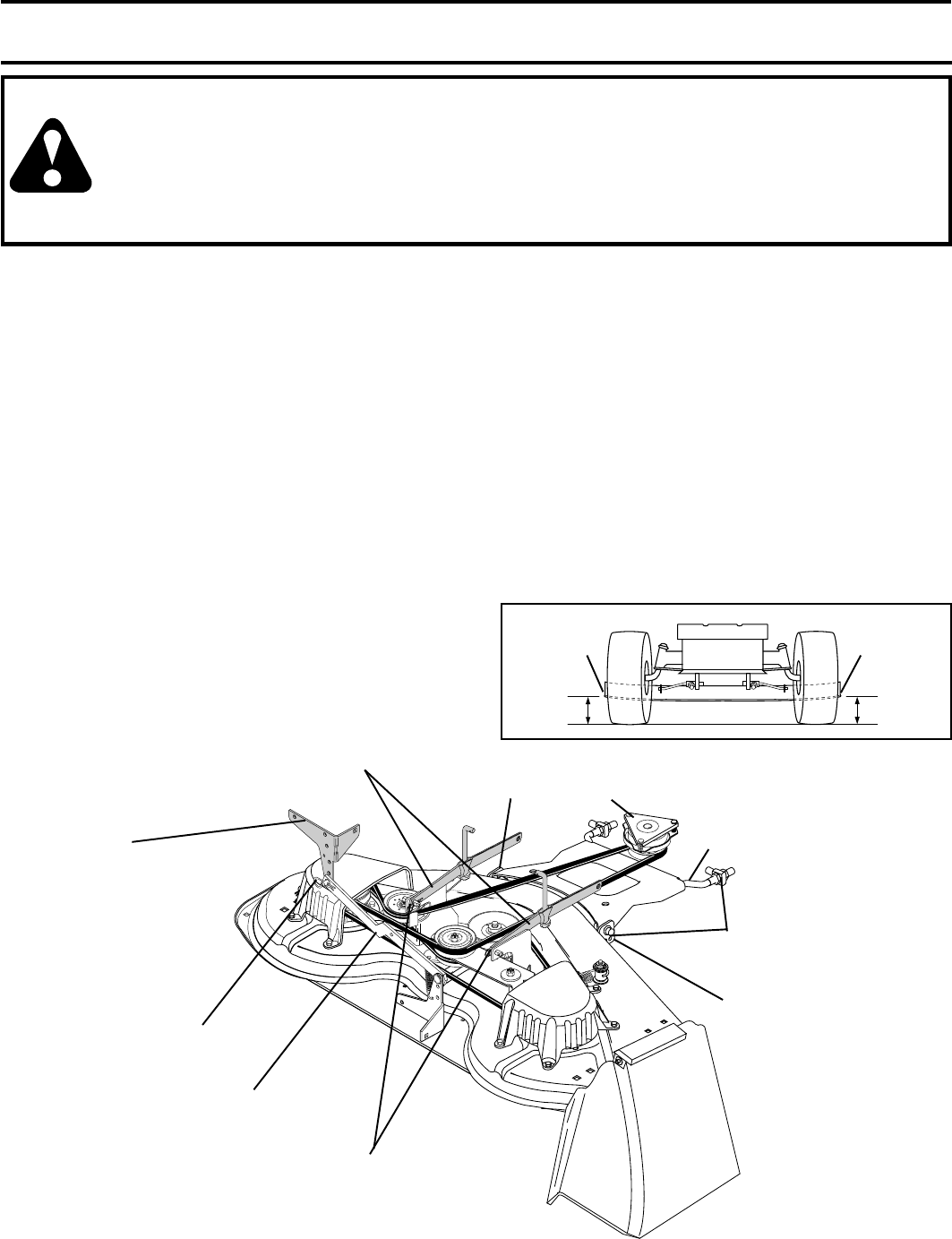
SIDE-TO-SIDE ADJUSTMENT (See Figs. 20 and 21)
• Raise mower to its highest position.
• Measure height from bottom of deck curl to ground level
at front corners of mower. Distance “A” on both sides of
mower should be the same.
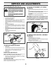
• If adjustment is necessary, make adjustment on one
side of mower only.
• To raise one side of mower, tighten lift link adjustment
nut on that side.
• To lower one side of mower, loosen lift link adjustment
nut on that side.
FIG. 21
A
A
GROUND LINE
FIG. 20
BOTTOM
EDGE OF
MOWER TO
GROUND
BOTTOM
EDGE OF
MOWER TO
GROUND
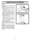
TRACTOR
SUSPENSION
ARMS
RETAINER
SPRING
ANTI-SWAY
BAR
RETAINER
SPRINGS
CHASSIS
BRACKET
RETAINER
SPRINGS
(BOTH SIDES)
FRONT
MOWER
BRACKET
FRONT
MOWER
BRACKET
ELECTRIC
CLUTCH
PULLEY
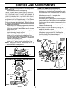
TO REMOVE MOWER (See Fig. 20)
• Place attachment clutch in “DISENGAGED” position.
• If equipped, t urn height adjustment knob to lowest
setting.
• Lower mower to its lowest position.
• Remove retainer spring holding anti-swaybar to chassis
bracket and disengage anti-swaybar from bracket.
• Remove four retainer springs from front plate assembly
and remove plate.
• Remove retainer springs from suspension arms at deck
and disengage arms from deck.
• Raise attachment lift to its highest position.
• Slide mower forward and remove belt from electric
clutch pulley.
• Slide mower out from under right side of tractor.
TO INSTALL MOWER
Follow procedure described in “INSTALL MOWER AND
DRIVE BELT” in the Assembly section of this manual.
FRONT
PLATE
ASSEMBLY