


8
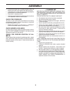
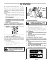
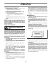
IMPORTANT: Check belt for proper routing in all mower
pulley grooves.
• If equipped, turn height ad just ment knob coun ter -
clock wise until it stops.
• Lower mower linkage with attachment lift control.
• Be sure belt tension rod is in dis en gaged position.
• Install belt into electric clutch pulley groove.
• Place the suspension arms on outward pointing deck
pins. Retain with double loop re tain er spring with loops
up as shown.
• Install front plate assembly to tractor suspension
brack ets and retain with single loop retainer springs
as shown.
• Position front plate assembly between front mower
brackets. Raise deck and plate assembly to align holes
and insert fl anged pins. Secure pins with double loop
retainer springs between the plate assembly and mower
brackets.
NOTE: To assist in locating hole in fl anged pin, the hole in
pin is inline with notch on head of pin.If necessary, move
mower side-to-side to give space between plate and mower
brackets.
IMPORTANT: Check belt for proper routing in all mower
pulley grooves. Engage belt tension rod by pushing rod
into locking bracket.
• Engage belt tension rod by pushing rod into locking
bracket.
CAUTION: Belt tension rod is spring
loaded. Have a tight grip on rod and
engage slowly.
ASSEMBLY
FIG. 5
FIG. 6
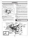
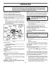
INSTALL MOWER AND DRIVE BELT
(See Figs. 6 and 7)
Be sure tractor is on level surface and mower suspension
arms are raised with attachment lift control. Engage park-
ing brake.
• Cut and remove ties securing anti-sway bar and belts.
Swing anti-sway bar to left side of mower deck.
• Slide mower under tractor with defl ector shield to right
side of tractor.
02510
ANTI-SWAY
BAR
SINGLE
LOOP
RE TAIN ER
SPRINGS
GAUGE
WHEEL
SUS PEN SION ARMS
DOUBLE LOOP
RE TAIN ER SPRING
FRONT
SUSPENSION
BRACKETS
FRONT PLATE
AS SEM BLY
CHAS SIS
BRACKET
DOUBLE LOOP
RETAINER SPRING
(OUTWARD POINTING
DECK PINS)
ELEC TRIC
CLUTCH PULLEY
DE FLEC TOR
SHIELD
USE PLIERS FOR
RETAINER
SPRINGS
LOOP UP
FRONT MOW-
ER BRACKET
BELT TEN SION ROD
(DISENGAGED PO SI TION)
LOCK BRACKET
FLANGED PIN
DOUBLE LOOP RE-
TAIN ER SPRING
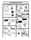
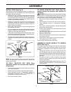
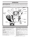
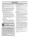
TO ATTACH NOSE ROLLER (See Fig. 5)
• Assemble brackets "A" and "B" to the inside of mower
mounting brack ets as shown. Tighten securely.
NOTE: Be sure bracket tabs are po si tioned in tab holes
in mower brackets.
• Position nose roller between brackets and install rod
and retainer spring.
02612
NOSE ROLLER
HEX BOLT
"A"
BRACKET
"B"
BRACKET
LOCK
NUT
TAB
HOLE
RETAINER SPRING
ROD