


7
ASSEMBLY
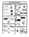
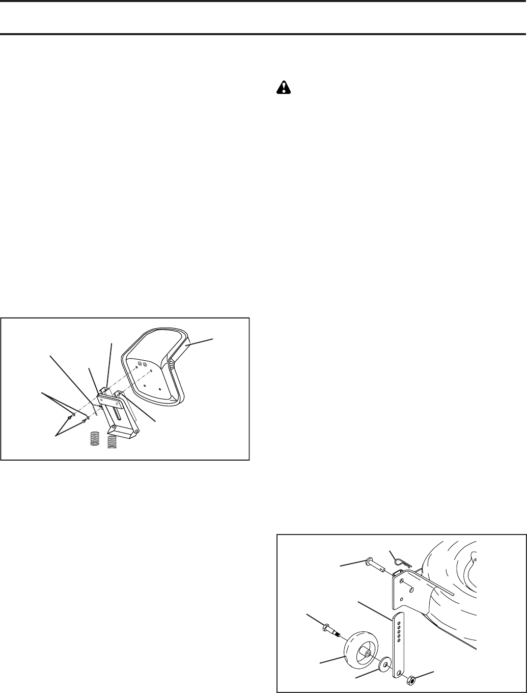
FIG. 4
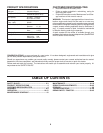
FIG. 3
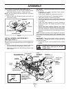
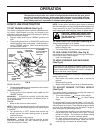
ASSEMBLE GAUGE WHEELS TO MOWER
DECK (See Fig. 4)
The gauge wheels are designed to keep the mower deck
in proper position when operating mower. Be sure they
are properly adjusted to ensure optimum mower per for -
mance.
• Slide gauge wheel bar down into bracket channel, Be
sure that gauge wheel bar aligning holes are on top.
As sem ble gauge wheels as shown using shoulder bolts,
3/8 washers and 3/8-16 center locknuts and tighten
securely.
• For ease of mower to tractor assembly, raise gauge
wheels to highest position and retain with clevis pins
and spring retainers.
• Adjust gauge wheels before operating mower. See “TO
ADJUST GAUGE WHEELS” in the Operation sec tion
of this manual.
SHOULDER
BOLT
GAUGE
WHEEL
3/8-16 CENTER
LOCKNUT
3/8 WASH ER
AD JUST ING
BAR
PIN
RETAINER SPRING
TO ROLL TRACTOR OFF SKID (See
Op er a tion section for location and function
of con trols)
• Press lift lever plunger and raise attachment lift lever
to its highest po si tion.
• Release parking brake by depressing brake ped al.
• Place freewheel control in free wheel ing po si tion to
dis en gage transmission (See “TO TRANSPORT” in
the Operation section of this manual).
• Roll tractor forward off skid.
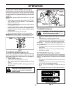
TO DRIVE TRAC TOR OFF SKID (See Op-
er a tion section for location and function of
con trols)
WARNING: Before start ing, read, un der stand and fol low
all in struc tions in the Op er a tion section of this man u al. Be
sure tractor is in a well-ventilated area. Be sure the area in
front of tractor is clear of other peo ple and objects.
• Be sure all the above assembly steps have been com-
pleted.
• Check engine oil level and fi ll fuel tank with gasoline.
• Place freewheel control in "transmission engaged"
po si tion.
• Sit on seat in operating position, depress brake pedal
and set the parking brake.
• Press lift lever plunger and raise attachment lift lever
to its highest position.
• Start the engine. After engine has started, move throttle
control to idle position.
• Release parking brake.
• Slowly move the mo tion control lever for ward and slowly
drive tractor off skid.
• Apply brake to stop tractor and set parking brake.
• Turn ignition key to "OFF" position.
Continue with the in struc tions that follow.
02521
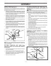
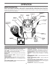
R.H. SEAT SLIDE
L.H. SEAT
SLIDE
SEAT
PAN
MOUNT ING
BOLTS
ADJUSTMENT
HANDLE
SEAT
INSTALL SEAT (See Fig. 3)
Seat position should be adjusted forward or backward so
that the operator can comfortably reach clutch/brake pedal
and safely operate the tractor.
• Remove the two (2) bolts and fl at washers securing
the seat to cardboard packing. Keep the two (2) bolts
only and place them with the two (2) identical bolts
and four (4) washers in the parts bag. Discard the fl at
washers and cardboard packing.
• Release L.H. seat slide on seat pan by pulling out on
adjustment handle and sliding it to the rear position
exposing seat mount ing holes from bot tom. Slide R.H.
slide to same rear position.
• Mount rear of seat on slides using mount ing bolts and
lock washers as shown.
• Pull out on adjustment handle and slide seat all the way
forward. Install front mounting bolts and lock washers.
Tight en all mounting bolts securely.
• Lower seat into operating position and sit on seat. Press
clutch/brake pedal all the way down. If operating posi-
tion is not comfortable, adjust seat.
• To adjust seat: Grasp adjustment handle and pull out,
slide seat to desired po si tion and release adjustment
handle.
LOCK
WASHERS
NOTE: You may now roll or drive your tractor off the skid.
Follow the appropriate instruction below to remove the
tractor from the skid.