


24
SERVICE AND ADJUSTMENTS
02232_Hydro
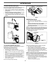
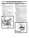
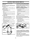
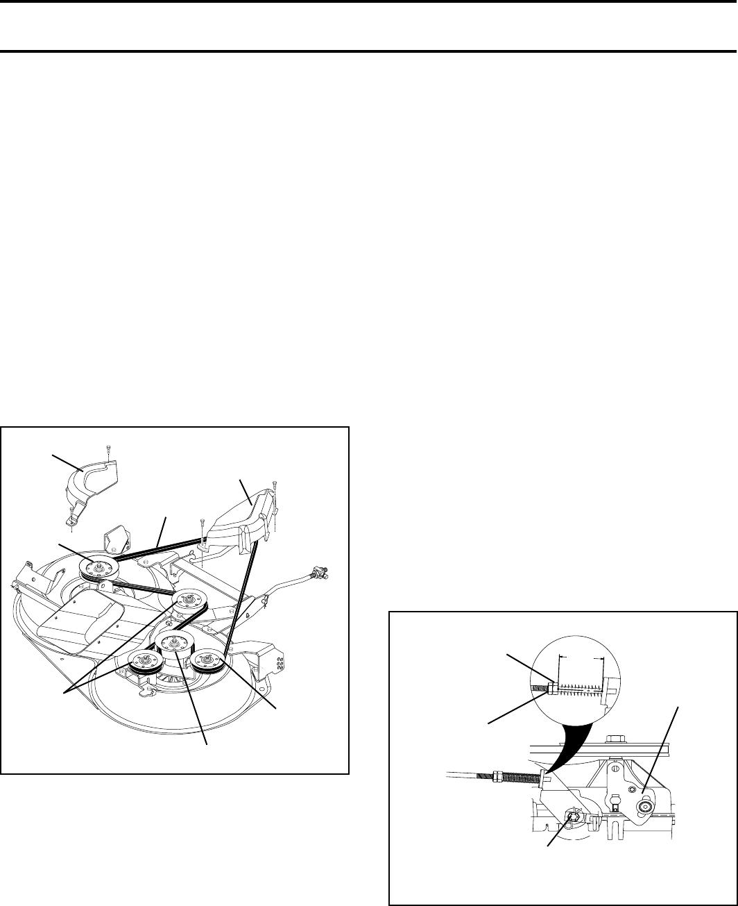
WITH PARKING BRAKE “ENGAGED”
JAM NUT
DO NOT TOUCH THIS NUT. IF FURTHER BRAKE
AD JUST MENT IS NECESSARY
CONTACT YOUR NEAR EST AU THO RIZED SER-
VICE CENTER/DEPARTMENT
OPERATING
ARM
NUT “A”
FIG. 30
1-9/16"
TO CHECK AND ADJUST BRAKE
(See Fig. 30)
Your tractor is equipped with an ad just able brake system
which is mounted on the right side of the transaxle.
If tractor requires more than fi ve (5) feet to stop at highest
speed in high est gear on a level, dry concrete or paved
surface, then brake must be checked and ad just ed.
TO CHECK BRAKE
• Park tractor on a level, dry concrete or paved surface,
depress clutch/brake pedal all the way down and en-
gage parking brake.
• Disengage transmission by placing freewheel control
in “transmission disengaged” position. Pull freewheel
con trol out and into the slot and release so it is held in
the disengaged position.
The rear wheels must lock and skid when you try to manually
push the tractor forward. If the rear wheels rotate, the brake
needs to be adjusted or the pads need to be replaced.
TO ADJUST BRAKE
• Depress clutch/brake pedal all the way down and en-
gage parking brake.
• Measure distance between brake operating arm and
nut “A” on brake rod.
• If distance is other than 1-9/16", loosen jam nut and
turn nut “A” until distance becomes 1-9/16". Retighten
jam nut against nut “A”.
• Engage transmission by placing freewheel control in
“trans mis sion engaged” position.
• Road test tractor for proper stopping distance as stated
above. Readjust if nec es sary. If stopping distance is
still greater than fi ve (5) feet in high est gear, further
main te nance is nec es sary. Replace brake pads or
contact a qualifi ed service center.
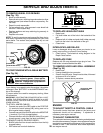
FIG. 29
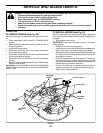
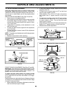
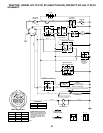
TO REPLACE MOWER BLADE DRIVE BELT
(See Fig. 29)
Park the tractor on level surface. Engage parking brake.
BELT REMOVAL -
• Remove mower from tractor (See “TO REMOVE
MOW ER” in this section of this manual).
• Remove screws from RH mandrel cover and remove
cover.
• Remove screws from LH mandrel cover and remove
cover.
• Work belt off both mandrel pulleys and idler pulleys.
• Pull belt away from mower.
BELT INSTALLATION -
• Install new belt in reverse order of removal. See belt
routing decal located on right mandrel cover.
• Make sure belt is in all pulley grooves and in side all
belt guides.
• Install left and right mandrel covers and tighten se cure ly.
Make sure belt is in mandrel pulley cover.
• Install mower (see "To install mower" in this section of
this manual).
LH MANDREL
COVER
BELT
MANDREL PULLEY
IDLER
PULLEY
RH MAN DREL COVER
MANDREL
PULLEY
IDLER
PULLEY