


5
IMPORTANT: OVERTIGHTENING THE SCREWS
ENOUGH TO CHANGE THE SHAPE
OF THE HANDLES CAN RESULT IN
DAMAGE TO THE ENGINE CASTING.
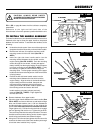
● Hold the curved head carriage bolt against theoutside of
the lower handle while tightening the tee knobs securely.
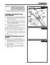
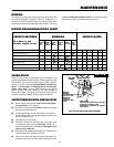
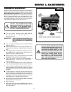
TO INSTALL THE THROTTLE CON-
TROL ASSEMBLY
● Place a No. 10 x 1-1/2 inch hex head screw down
through the hole in the upper handle right side and
attach the throttle control to the underside of the
handle (See FIG. 4-ASSY).
● Attach the throttle cable to the right lower handle by
threading a tie strap through the hole in the lower
handle and around the throttle cable on the outside
of the handle (See FIG. 4-ASSY).
● Thread the pointed end of the strap through the
other (square) end of the strap and pull tight around
the throttle cable and lower handle.
NOTE: One side of the tie strap is rough, while the other side
is smooth. The rough side must be on the inside of the loop
formed when the ends of the tie strap are put together.
● Try to loosen the tie strap. If it will loosen, it is put
together with the smooth side to the inside of the
loop. Remove the tie strap and reverse the direc-
tion.
● Cut off excess strap.
TEE
KNOB
11/32 INCH
FLATWASHER
HEX
NUT
NO. 10 X 1-1/2 INCH
HEX HEAD SCREW
HANDLE
GRIP
THROTTLE
CONTROL
FORMED
WASHER
CURVED HEAD
CARRIAGE
BOLT
TIE STRAP
LEFT LOWER
HANDLE
HANDLE
GRIP
UPPER
HANDLE
FIG. 4-ASSY
ASSEMBLY
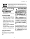
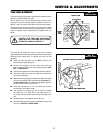
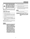
TO INSTALL THE REMOTE SHUT-OFF
SWITCH
● Assemble shut off switch (See FIG. 5-ASSY).
● Attach assembled switch to left lower handle (switch on
inside of handle) with a No. 10x1-1/16 inch hex head
screw and a No. 10 keps nut. Tighten securely.
● Push switch wire onto prong on bottom side of switch
(See FIG. 5-ASSY).
● Attach switch wire to left lower handle (See FIG. 6-
ASSY) as close to the engine casting as possible with a
cable tie strap.
RIGHT LOWER
HANDLE
FIG. 5-ASSY
FIG. 6-ASSY