10
ASSEMBLY
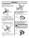
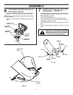
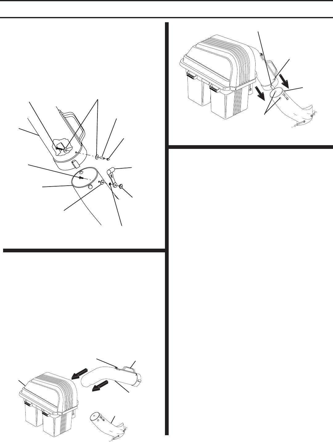
CHUTE LATCH ASSEMBLY
(See Fig. 8)
Use Hardware - - GROUPS "E & F"
• Assemble latch pin to upper chute, as shown.
• Press weld nut into rubber latch and assemble rubber
latch to lower chute, as shown.
• Tighten all hardware securely.
UPPER
CHUTE
LOCK WASHER
WELD
NUT
ACORN NUT
SPLIT
SPACER
WASHERS
3/16 x 3/4 x 16 Ga.
#10 x 1-1/8" SCREW
WASHER
3/16 x 3/4 x 16 Ga.
LOWER CHUTE
#10 x 5/8"
SCREW
RUBBER
LATCH
8
FIG. 8
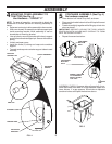
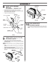
UPPER CHUTE (See Figs. 9A & 9B)
No hardware required
• Lower mower deck to its lowest cutting position.
• Assemble upper chute by inserting curved end into hole
in back of cover.
NOTE: Handle carefully so as not to damage dump bag
indicator.
• Push in and turn upper chute until it is in line with lower
chute.
• Align the bosses on lower chute with alignment slots on
upper chute and slide together.
• Secure with rubber latch by hooking hole in latch over
latch pin.
9
HANDLE
DUMP BAG
INDICATOR
UPPER
CHUTE
COVER
LOWER
CHUTE
FIG. 9A
BOSSES
LATCH PIN
ALIGNMENT
SLOT
RUBBER
LATCH
FIG. 9B
LEVEL MOWER DECK
No hardware required
• Be sure deck is properly leveled for best mower perfor-
mance. See your tractors owner's manual for instruc-
tions.
10


