8
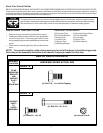
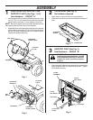
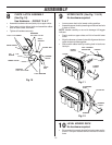
CONTAINER ASSEMBLY (See Fig. 6)
No hardware required
• Place bottom half inside of top half, as shown.
• Place one foot inside bottom half and lift top half to meet
bottom half.
• Press halves tightly together while lifting top to lock into
place as shown.
IMPORTANT: BEFORE LOCKING THE TABS, HOOKED
EDGES ON BOTH HALVES MUST OVERLAP TO FORM
SEAL AS SHOWN IN INSET.
• Repeat for second container.
5
PRESS TOGETHER
TO FORM SEAL
WHILE LIFTING
TOP HALF
CONTAINER
BOTTOM
HALF
CONTAINER
BOTTOM
HALF
CONTAINER
TOP HALF
ASSEMBLY CHECK: Squeeze sides of lower half of con-
tainer and check that there is no gap between upper and
lower halves. If a gap appears, unlock tabs to separate
container halves and repeat instructions above.
LOCKING
TAB
W
A
R
N
I
N
G
D
o
n
o
t
o
p
e
r
a
t
e
m
o
w
e
r
u
n
l
e
s
s
c
o
n
t
a
i
n
e
r
i
s
p
r
o
p
e
r
l
y
i
s
n
s
t
a
l
l
e
d
.
C
o
n
t
a
i
n
e
r
i
s
s
u
b
j
e
c
t
t
o
w
e
a
r
a
n
d
d
e
t
i
e
r
i
o
r
a
t
i
o
n
.
C
h
e
c
k
b
a
g
f
r
e
q
u
e
n
t
l
y
.
R
e
p
l
a
c
e
w
h
e
n
c
r
a
c
k
e
d
o
r
d
a
m
a
g
e
d
.
U
s
e
o
n
l
y
a
r
e
c
o
m
m
e
n
d
e
d
r
e
p
l
a
c
e
m
e
n
t
c
o
n
t
a
i
n
e
r
.
Fig. 6
ASSEMBLY
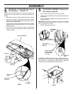
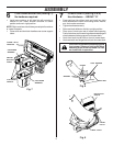
MOUNTING TO TRACTOR (See Fig. 5)
Use Hardware - - GROUP "C"
NOTE: For ease of assembly, you may wish to obtain the
assistance of another person for mounting assembly to
tractor.
• Raise seat on tractor to allow assembly to be mounted.
• With cover closed, lift assembly and place support
posts into mounting bracket. Allow assembly to rest on
bottom of mounting bracket.
• Line up holes in mounting bracket with holes in support
posts and insert support post clevis pins. Secure with
retainer springs.
• Install the four (4) tubing end caps onto container
support. Tap each end cap onto container support tubes
to seat securely.
4
COVER ASSEMBLY
Fig. 5
END CAP
SUPPORT
POST
MOUNTING
BRACKET
SUPPORT
POST
CLEVIS
PINS
RETAINER
SPRINGS
DRAWBAR


