


5
ASSEMBLY
With the exception of handlebars, controls and transport kit, your new tiller has been completely
assembled at the factory. It should be noted that right and left sides are determined by the operators
position behind the unit.
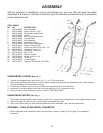
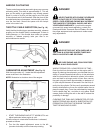
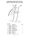
HANDLEBARS (LOWER)
(See Fig. 1)
1. Place a curved washer onto each of two (2) 1/4” x 4 1/2” hex head bolts.
2. Place lower handlebar (left hand) into position below engine and insert both hex head bolts with curved washers,
through handlebar and transmission housing.
3. Place lower handlebar (right hand) into position over exposed ends of hex head bolts.
4. Install two (2) curved washers over bolts and follow with tow (2) 1/4” indented loc nuts.
5. Snug loc nuts to hold handlebars in place---DO NOT TIGHTEN FIRMLY.
HANDLEBARS (UPPER) (See Fig. 1)
1. Place upper handle between lower handles. Install two (2) curved head carriage bolts to hold upper handle in place.
2. Secure carriage bolts with two (2) curved washers and plastic tee knobs.
3. Next, firmly tighten lower loc nuts against handlebars until all handlebar “play” has been eliminated.
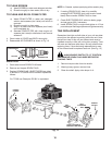
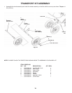
ASSEMBLY—DRAG STAKE/WHEEL TRANSPORT
1. Mount drag stake onto bracket with clevis pin and hairpin cotter pin. See Fig. 20 on page 16 for assembly
sequence.
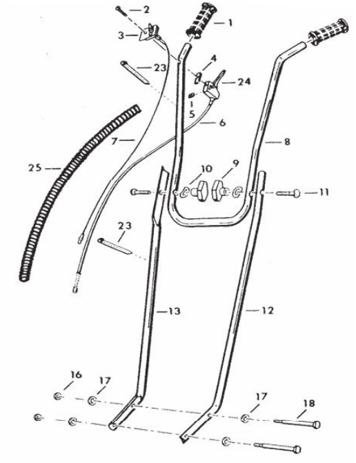
Fig. 1
ITEM ORDER
NO. NO. DESCRIPTION
1 505 29 00-01 Grip, Handlebar
2 505 29 00-02 Screw, #10-24 x 1 3/8
3 505 29 00-03 Switch Assy, w/Mtg Plate
4 505 29 00-04 Isolator
5 505 29 00-05 Nut, Throttle/Switch Assy
6 505 29 00-06 Throttle Cable
7 505 29 00-07 Wire Assembly
8 505 29 00-08 Handlebar, Upper
9 505 29 00-09 Knob, Plastic, Handlebar
10 505 29 00-10 Washer, Curved Knob
11 505 29 00-11 Screw, Curved Hd 5/16-18 x 1 1/2
12 505 29 00-12 Handlebar, Lower L.H.
13 505 29 00-13 Handlebar, Lower R.H.
16 505 29 00-14 Nut, 1/4-20
17 505 29 00-10 Washer, Curved
18 505 29 00-15 Screw, 1/4-20 x 4 1/2
23 505 29 00-59 Tie Strap
24 505 29 00-16 Throttle Trigger
25 505 29 00-17 Housing, Wire Assy & Thrl Cable