


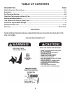
6
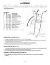
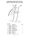
THROTTLE CABLE
Unwind throttle cable from around engine.
CAUTION: Be careful not to kink cable.
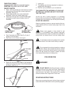
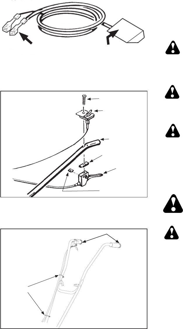
ON/OFF SWITCH
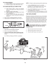
1. Place 1 3/8” long slotted pan head screw into switch
plate and down through hole in upper right hand
handlebar. (See Fig. 2)
2. Place rubber isolator over screw underneath
handlebar. Follow with throttle trigger body.
3. Place flat nut though slot in side of throttle trigger
and tighten screw to secure throttle control to
handlebar.
As with any item of power equipment, it is necessary
that you learn and observe ALL Safety precautions. This
includes care of the machine as well as personal safety.
DO NOT BE CARELESS!
Read the operating instruction manual carefully. Be thor-
oughly familiar with the controls and proper use of the
equipment.
PRE-OPERATION
STARTING INSTRUCTIONS
Be sure you are using the proper fuel and have read and
under stand all the instructions on the preceding pages.
It is advisable to wear a long sleeve shirt or jacket.
Don’t wear shorts. Don’t wear loose clothing or jewelry.
DANGER!
DO NOT SMOKE while filling the tank, or starting
the engine. Be sure the proper fuel is used. Read the fuel
instructions in the manual and/or on the engine. Always
store the fuel to be used in this machine in a properly
marked container that is approved for such use.
Always wear goggles or face shield for eye
protection. It is advisable to wear protective head gear.
These precautions are used to prevent the possibility of
being struck by objects thrown from the rotating tines.
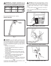
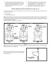
4. Push 2 terminals of kill wire (See Fig. 3) onto 2
prongs of shut off switch.
5. Push other end of kill wire onto engine.
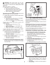
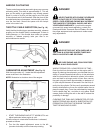
6. Retain kill wire and throttle cable to right handle bar
using two (2) nylon tie straps. Cut off loose ends of
the straps. (See Fig. 4)
Do not operate this unit when barefoot or wearing
open sandals. Always wear substantial footwear; leather
work shoes or short boots function well for most people.
Either will help protect the operator’s ankles and shins
from objects being thrown by rotating tines.
7. Install grips.
8. Tine spacers provided can be placed in toolbox or
garage shelf (see page 9).
8. Fuel mix cup is provided for your convenience.
THIS COMPLETES THE ASSEMBLY OF YOUR UNIT.
RE-CHECK ALL SCREWS AND NUTS TO BE SURE
THEY ARE TIGHT.
Fig. 2
Fig. 4
TIE STRAPS
GRIPS
CONNECTION
AT ENGINE END
CONNECTION AT
SWITCH END
KILL WIRE
Fig. 3
FLAT NUT
RUBBER
ISOLATOR
HANDLEBAR
SWITCH
SCREW
THROTTLE
CONTROL