


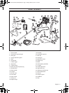
ASSEMBLY
English – 13
Assembling the cutting
equipment
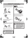
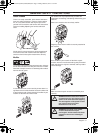
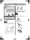
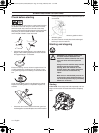
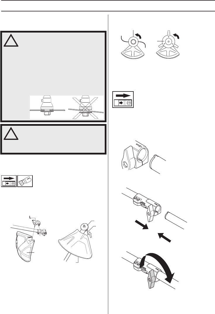
Fitting the trimmer guard and
trimmer head
• Fit the correct trimmer guard (A) for use with the
trimmer head. Hook the trimmer guard/combination
guard onto the fitting on the shaft and secure with the
bolt (L).
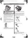
• Fit the drive disc (B) on the output shaft.
• Turn the output shaft until one of the holes in the drive
disc aligns with the corresponding hole in the gear
housing.
• Insert the locking pin (C) in the hole to lock the shaft.
• Screw on the trimmer head/plastic blades (H) in the
opposite direction to the direction of rotation.
• To dismantle, follow the instructions in the reverse
order.
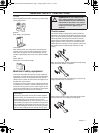
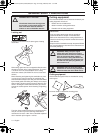
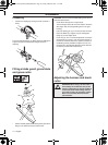
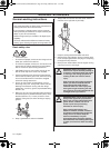
Assembling and dismantling the
two-piece shaft (525 RJD)
Assembly
• Loosen the coupling by turning the knob.
• Align the tab of the attachment (A) with the arrow on
the coupling (B).
• Push the attachment into the coupling until the
attachment snaps into place.
• Before using the unit, tighten the knob securely.
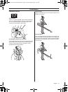
!
WARNING!
When fitting the cutting attachment it is
extremely important that the raised
section on the drive disc/support flange
engages correctly in the centre hole of
the cutting attachment. If the cutting
attachment is fitted incorrectly it can
result in serious and/or fatal personal
injury.
!
WARNING! Never use a cutting
attachment without an approved guard.
See the chapter on Technical data. If an
incorrect or faulty guard is fitted this can
cause serious personal injury.
A
A
B
C
H
H
A
B
H1155734-26,524L,525LST,RJD,.fm Page 13 Friday, March 8, 2013 7:19 AM