


English---13
115275126 Rev. 1 9/15/09
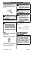
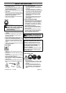
ASSEMBLY
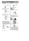
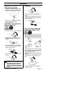
Dismantling:
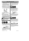
S Loosen the coupling by turning the knob.
S P ress and hold the locking/release but-
ton (A).
S W hile securely holding the engine and
upper shaft, pull the attachment straight
out of the coupling.
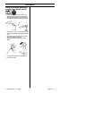
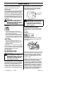
Assembling and dismantling
the two-- piece shaft
Assembly:
S Loosen the coupling by turning the knob.
S P osition locking/release button (A) of
attachment into guide recess (B) of
coupling.
S P ush the attachment into the coupling
until the locking/release button snaps
into the primary hole (C).
S B efore using the unit, tighten the knob
securely.
A
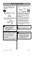
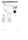
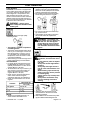
S Fit the drive disc (F) on the output shaft.
S Turn the shaft until one of the holes in the
drive disc aligns with the corresponding
hole in the gear housing.
S Insert hex wrench (G) in the hole to lock
the shaft.
S Screw on the trimmer head (H) in the op-
posite direction to the direction of rota-
tion.
N
O
TE: Make sure unit is assembled cor-
rectly as shown in this manual.
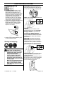
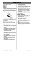
Fitting the loop hand le
S P osition the handle on the upper shaft.
Note that the handle must be mounted
between the two arrows on the shaft.
S F it the screw , securing plate and wing
nut as shown in the diagram.
S Tighten the wing nut.
D
E
D
F
G
H
S To dismantle, follow the instructions in
the reverse order.
Fitting the trimmer guard and
trimmer head (Model 128LD)
S F it the correct trimmer guard (D) for use
with the trimmer head. Hook the trimmer
guard/combination guard onto the fitting
on the shaft and secure with the bolt (E).
B
A
C
W ARNING: All attachments are
designedtobeusedintheprimary
hole unless otherwise stated in the
applicable attachment instruction
manual . Using the wrong hole could
lead to serious injury or damage to
the unit.