


13
ENGINE
ENGINE SPEED
Your engine speed has been factory set. Do not attempt to
increase engine speed or it may result in personal injury. If
you believe that the engine is running too fast or too slow,
take your lawn mower to an authorized service center for
repair and adjustment.
THROTTLE CONTROL
If it becomes necessary to adjust or replace the throttle
control, see the adjustment section of your engine manual.
CARBURETOR
Your carburetor is not adjustable. If your engine does not
operate properly due to suspected carburetor problems, take
your lawn mower to an authorized service center for repair
and/or adjustment.
IMPORTANT: NEVER TAMPER WITH THE ENGINE
GOVERNOR, WHICH IS FACTORY SET FOR PROPER
ENGINE SPEED. OVERSPEEDING THE ENGINE ABOVE
THE FACTORY HIGH SPEED SETTING CAN BE
DANGEROUS. IF YOU THINK THE ENGINE-GOVERNED
HIGH SPEED NEEDS ADJUSTING, CONTACT YOUR
NEAREST AUTHORIZED SERVICE CENTER, WHICH HAS
PROPER EQUIPMENT AND EXPERIENCE TO MAKE ANY
NECESSARY ADJUSTMENTS.
SERVICE AND ADJUSTMENTS
CAUTION: BEFORE PERFORMING ANY SERVICE OR ADJUSTMENTS:
1. Release control bar and stop engine.
2. Make sure the blade and all moving parts have completely stopped.
3. Disconnect spark plug wire from spark plug and place where it cannot come in contact with plug.
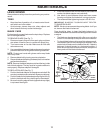
LAWN MOWER
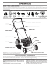
TO ADJUST CUTTING HEIGHT
See “TO ADJUST CUTTING HEIGHT” in the Operation
section of this manual.
REAR DEFLECTOR
The rear deflector, attached between the rear wheels of your
mower, is provided to minimize the possibility that objects
will be thrown out of the rear of the mower into the operator's
mowing position. If the deflector becomes damaged, it
should be replaced.
DISCHARGE GUARD
The discharge guard, attached to the discharge opening of
your lawn mower, is provided to prevent the possibility of
injury resulting from objects being thrown out of the dis-
charge opening into the operator mowing position. If the
discharge guard becomes damaged, it should be replaced.
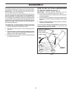
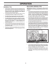
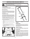
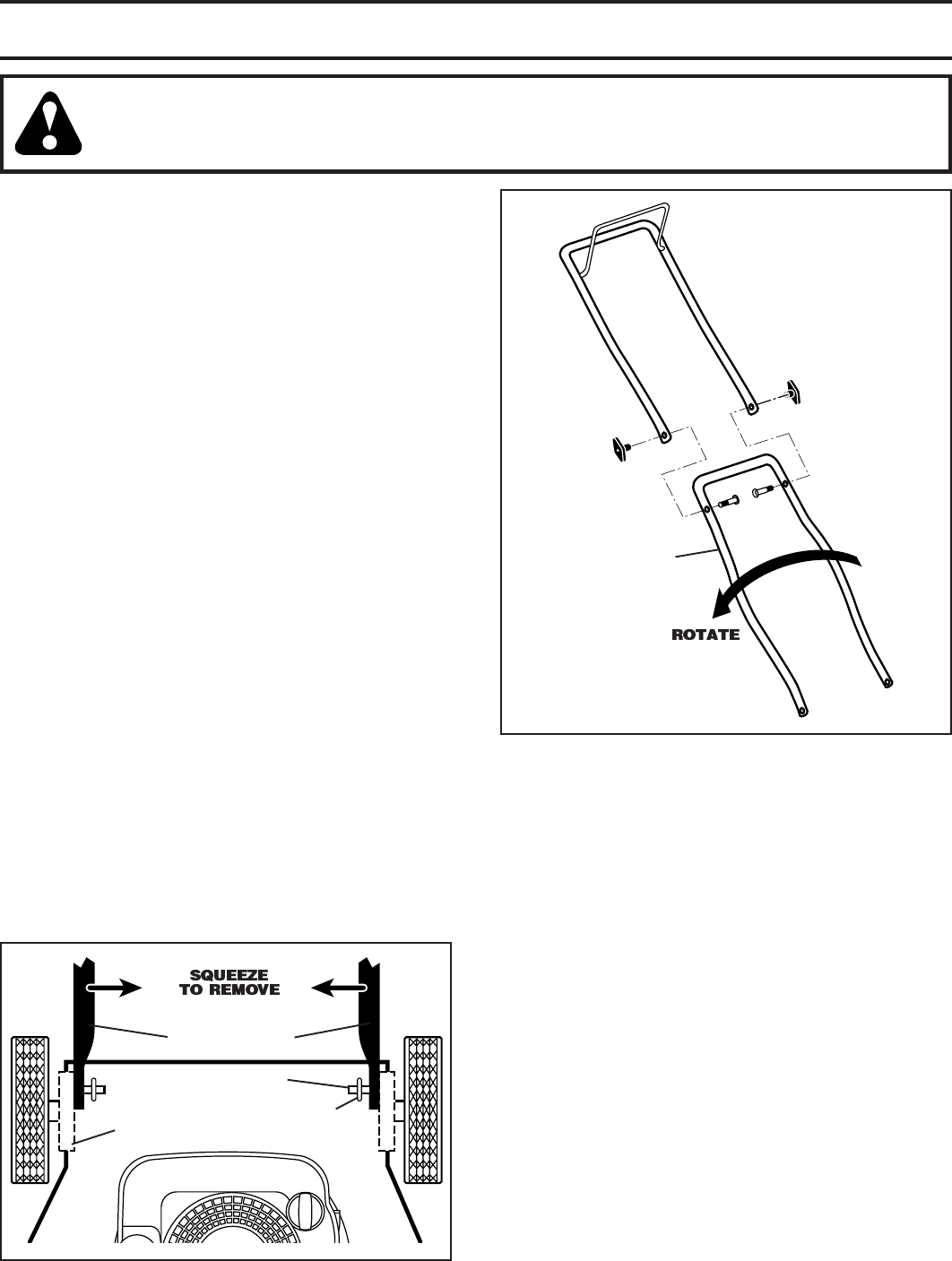
TO ADJUST HANDLE (See Figs. 9 and 10)
The handle can be mounted in a high or low position. The
mounting holes in the bottom of lower handle are off center
for raising or lowering the handle.
1. Remove upper handle and all parts attached to lower
handle.
2. Remove hairpin cotters from lower handle bracket mount-
ing pin.
3. Squeeze lower handle in to remove it from mounting
pins.
4. Turn lower handle over to raise or lower handle.
5. Squeeze lower handle in and position holes onto mount-
ing pins on handle bracket.
6. Reassemble upper handle and all parts removed from
lower handle.
FIG. 9
LOWER HANDLE
HAIRPIN
COTTER
MOUNTING PIN
HANDLE
BRACKET
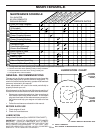
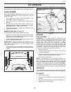
FIG. 10
LOWER
HANDLE