


9
PROEDGE SERIES BLADES
The ProEdge Line of beveled diamond blades is especially designed for architectural scoring to replace labor-intensive hand
tooling. These specialty blades are ideal for residential and commercial applications to chase standard joints for a beveled look.
Chasing cuts using the ProEdge blades would begin the next day or later after the concrete is placed and control joints have
been made. Choose the correct specication of ProEdge blade to suit your particular needs
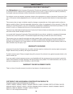
ProEdge V-Blade XL5-V21-X50 3/8” (9.53mm) wide bevel blade for existing 0.100” (2.54mm) wide saw cut
XL5-V23-X50 5/8” (15.88mm) wide bevel blade for existing 0.100” (2.54mm) wide saw cut
XL5-V25-X50 5/8” (15.88mm) wide bevel blade for existing 0.250” (6.35mm) wide saw cut
ProEdge Radius Blade XL5-R250-X50 5/8” (15.88mm) wide bevel blade for existing 0.100” (2.54mm) wide saw cut
XL6-R500-X50 3/4” (19.1mm) wide bevel blade for existing 0.100” (2.54mm) wide saw cut
Choose the correct specication of ProEdge Blade based on the width of the pre-existing control joint as follow:
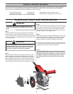
USING THE PROEDGE SERIES BLADES
Follow the instructions for installing a Excel series blade and
skid plate when installing a ProEdge blade.
NOTE:
The ProEdge blade requires its own unique skid plate to
function properly.
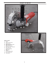
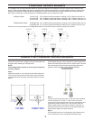
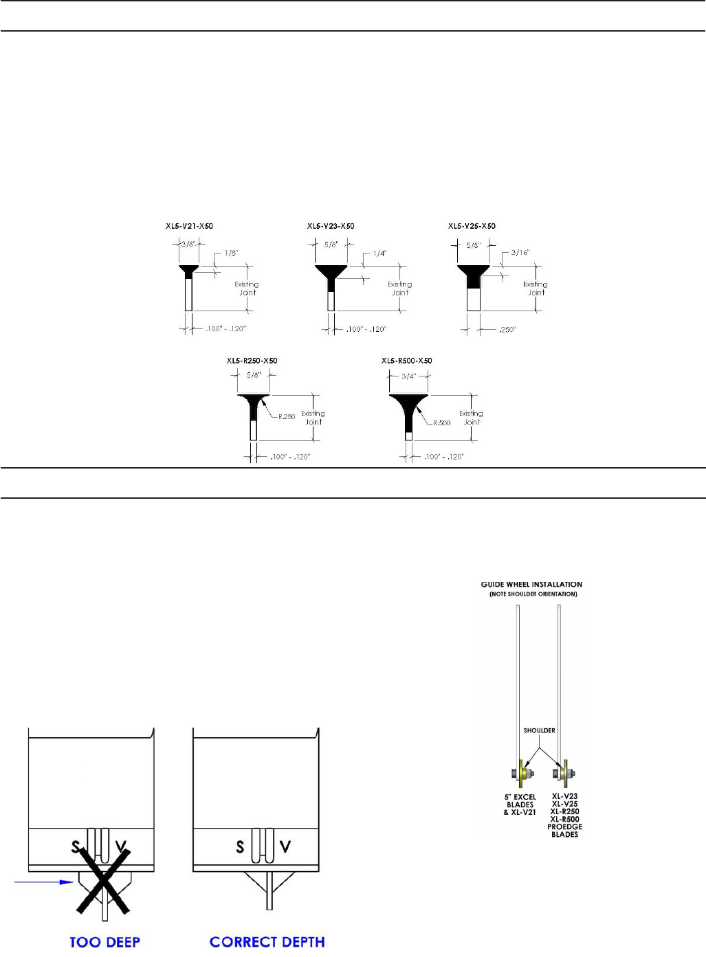
Step 1
Adjust bevel depth of cut by loosening the depth adjust arm.
Pull up on the lower guard until the proper amount of blade
protrudes below the skid plate. (See gure below for proper
depth).
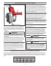
Step 3
Line up the saw by pushing down on the saw lower the blade
into the existing cut. Use the “V” notch on the front of the
lower guard to ne tune alignment. Flip the lock-off button and
squeeze the paddle switch to turn “ON” the saw. Allow the
blade to reach maximum speed the rotate the saw down to
plunge the blade into the concrete until the depth adjust arm
bottoms down against the depth stop bolt.
Step 4
Push the saw forward to cut, keeping the guide wheel on the
cut line. Maintain an even cutting speed for best results.
Step 2
Set the depth adjust arm rmly against the depth stop bolt and
tighten the depth adjust thumb screw to set the depth. Remove
the guide wheel and reinstall with the shoulder against the
guide arm (See illustration: Guide wheel installation).