


14 – English
ASSEMBLY
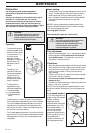
It is extremely important
that the disc drive’s/support
flange’s guide engages
correctly in the cutting
equipment’s centre hole
when assembling the cutting
equipment. Cutting
equipment assembled
incorrectly can result in
serious and/or fatal personal
injury.
!
WARNING!
Under no circumstances may the cutting
equipment be used without an approved
guard fitted. See the chapter
“Technical
data”
. If the wrong guard or a defective
guard is fitted this can cause serious
personal injury.
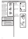
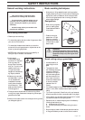
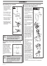
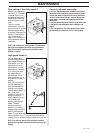
• Clip the loop handle onto
the shaft. Note that the
loop handle must be
fitted between the arrows
on the shaft.
• Slide the spacer into the
slot in the loop handle.
• Fit the nut, knob and
bolt. Do not overtighten.
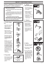
• Attach the J-handle to the
loop handle using the
three screws, as shown.
• Now adjust the trimmer
to give a comfortable
working position. Tighten
the bolt/knob.
Assembling the J-handle
!
WARNING
Only grass blades or trimmer heads/
plastic blades may be used when the J-
handle is fitted. Clearing blades must
never be used with the J-handle.
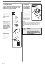
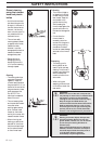
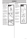
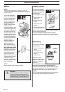
Assembling the spray guard and
trimmer head Superauto II
• Fit the guard (A) intended
for use with the trimmer
head. Hook the guard onto
the shaft fitting and secure
it with the bolt (L).
• Fit the drive disc (B) on the
output axle.
• Turn the blade axle until
one of the holes in the
drive disc aligns with the
hole in the gear housing.
• Insert the locking pin (C)
in the hole so that the axle
is locked.
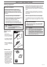
• The trimmer head must be
split to be fitted (see the
diagram). Proceed as
follows:
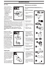
• Insert your finger into the
centre hole of the cover (I)
at the same time as you
hold the cover with your
other fingers. Press the two
catches (J) that extend from
the cut-out on the bottom
section (K) using the
thumb and index finger of
your other hand. Press
apart the trimmer head
using the fingers on the
cover.
• Place the cover (I) and the
support flange (F) on the
output axle.
• Fit the nut (G). The
tightening torque of the
nut is 35-50 Nm (3,5-5
kpm). Use the socket
spanner in the tool kit.
Hold the handle of the
spanner as close to the
trimmer guard as possible.
The nut is tightened when
the spanner is turned
against the direction of
rotation (left-hand thread).
• Fit the trimmer head‘s
bottom section (K) on the
cover (I) by pressing the
two sections together with
K
J
I
G
F
I
A
K
B
C
the cut-outs on the bottom section aligned with the catches
on the cover.
• To dismantle follow the instructions in the reverse order.
Assembly of the blade and trimmer
head