


English – 11
ASSEMBLY
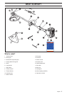
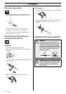
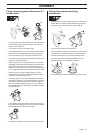
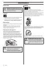
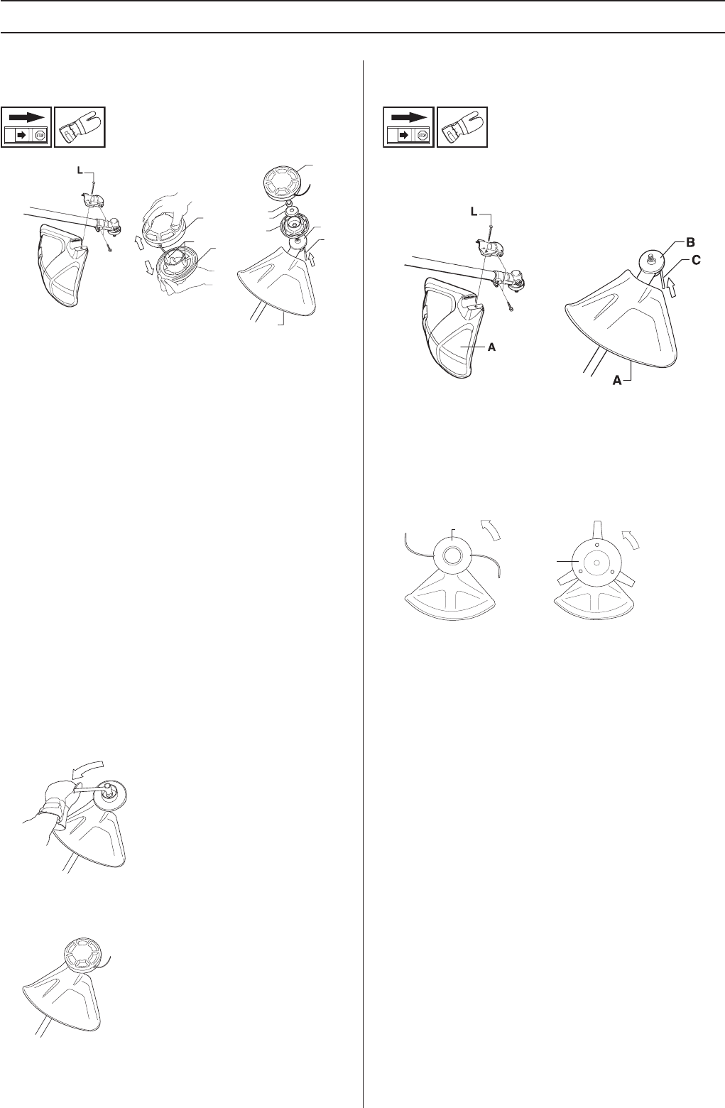
Fitting a trimmer guard and Superauto II 1"
trimmer head
• Fit the correct trimmer guard (A) for use with the trimmer
head. Hook the guard onto the fitting on the shaft and
secure it with the bolt (L).
• Fit the drive disc (B) on the output shaft.
• Turn the blade shaft until one of the holes in the drive disc
aligns with the corresponding hole in the gear housing.
• Insert the locking pin (C) in the hole to lock the shaft.
• To fit the trimmer head, first separate the two halves (see
diagram). Proceed as follows:
• Insert a finger into the centre hole of the cover (I) while
grasping the cover with your other fingers. Using the index
finger and thumb of your other hand, release the two
catches (J) that engage in the cut-outs in the bottom half
(K). Pull apart the trimmer head, grasping the cover firmly.
• Place the cover (I) and the support flange (F) on the
output shaft. Ensure that the drive disc’s guide locates
correctly in the cover’s centre hole.
• Fit the nut (G). The nut must be tightened to a torque of
35-50 Nm (3.5-5 kpm). Use the socket spanner in the tool
kit. Hold the shaft of the spanner as close to the blade
guard as possible. To tighten the nut, turn the spanner in
the opposite direction to the direction of rotation (Caution!
left-hand thread).
• Fit the bottom half of the trimmer head (K) to the cover (I)
by pressing them together, with the cut-outs on the bottom
half aligned with the catches on the cover.
• To dismantle, follow the instructions in the reverse order.
Fitting other guards and cutting
attachments
• Fit the correct trimmer guard (A) for use with the trimmer
head. Hook the trimmer guard/combination guard onto
the fitting on the shaft and secure with the bolt (L).
• Fit the drive disc (B) on the output shaft.
• Turn the blade shaft until one of the holes in the drive disc
aligns with the corresponding hole in the gear housing.
• Insert the locking pin (C) in the hole to lock the shaft.
• Screw on the trimmer head/plastic blades (H) in the
opposite direction to the direction of rotation.
• To dismantle, follow the instructions in the reverse order.
G
F
I
A
B
C
K
J
I
K
H
H