


English – 15
ASSEMBLY
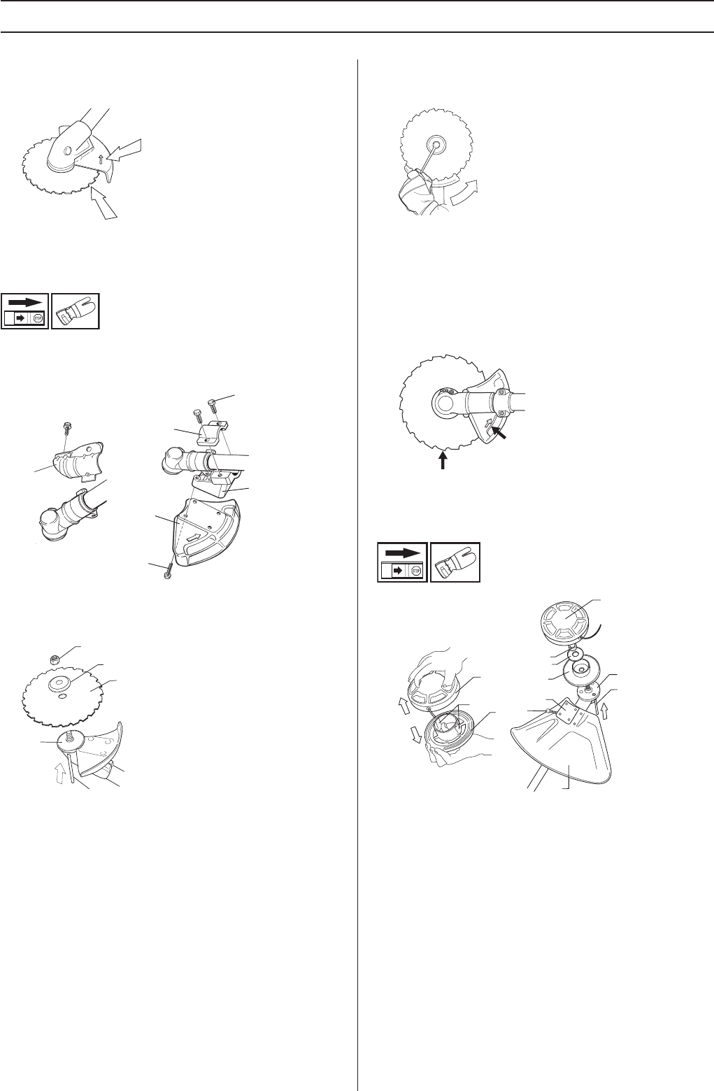
arrow in the diagram shows the area where you should
operate the socket spanner when loosening or tightening
the nut.
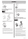
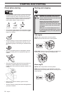
Fitting the blade guard and saw
blade (235R, 235FR)
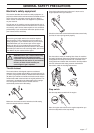
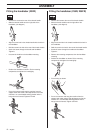
• Remove the mounting plate (H). Fit the adapter (I) and
bracket (J) with the two screws (K) as shown. Fit the blade
guard (A) to the adapter using the 4 screws (L) as shown.
CAUTION! Always use the recommended guard for the
cutting attachment you are using. See chapter on
Technical data.
• Fit the drive disc (B) on the output shaft.
• Turn the blade shaft until one of the holes in the drive disc
aligns with the corresponding hole in the gear housing.
• Insert the locking pin (C) in the hole to lock the shaft.
• Place the blade (D) and support flange (F) on the output
shaft.
• Fit the nut (G). The nut must be tightened to a torque of
35-50 Nm (3.5-5 kpm). Use the socket spanner in the tool
kit. Hold the shaft of the spanner as close to the blade
guard as possible. To tighten the nut, turn the spanner in
the opposite direction to the direction of rotation (Caution!
left-hand thread).
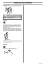
• When loosening and tightening the saw blade nut, there is
a risk of injury from the teeth of the saw blade. You should
therefore always ensure that your hand is shielded by the
blade guard when doing this. Always use a socket
spanner with a shaft that is long enough to allow this. The
arrow in the diagram shows the area where you should
operate the socket spanner when loosening or tightening
the nut.
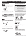
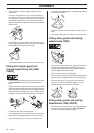
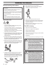
Fitting a trimmer guard and
Superauto II 1” trimmer head (232R)
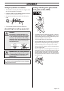
• Fit the correct trimmer guard (A) for use with the trimmer
head. Secure the trimmer guard using the 4 screws (L)
and the support plate (M) as shown.
• Fit the drive disc (B) on the output shaft.
• Turn the blade shaft until one of the holes in the drive disc
aligns with the corresponding hole in the gear housing.
• Insert the locking pin (C) in the hole to lock the shaft.
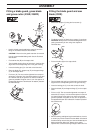
• To fit the trimmer head, first separate the two halves (see
diagram). Proceed as follows:
• Insert a finger into the centre hole of the cover (I) while
grasping the cover with your other fingers. Using the index
finger and thumb of your other hand, release the two
catches (J) that engage in the cut-outs in the bottom half
(K). Pull apart the trimmer head, grasping the cover firmly.
A
L
I
J
K
H
F
D
B
C
G
G
F
I
M
L
A
K
B
C
K
J
I