


English – 13
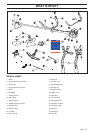
ASSEMBLY
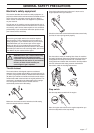
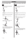
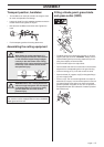
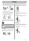
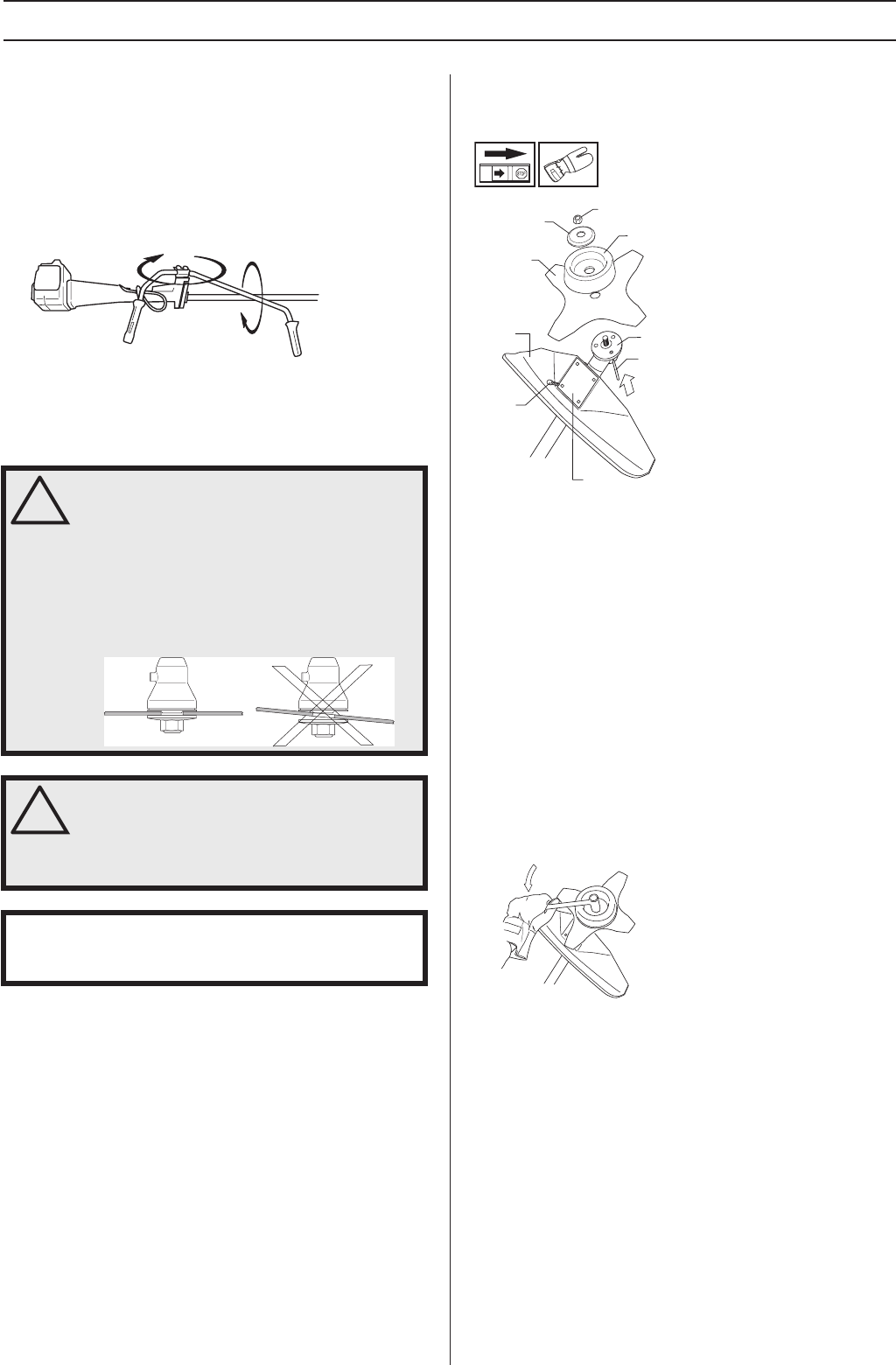
Transport position, handlebar
• The handlebar can easily be turned to fit along the shaft
for easier transportation and storage.
• Loosen the knob. Turn the handlebar clockwise so that the
throttle handle rests against the engine.
• Now twist the handlebar around the shaft. Tighten the
knob.
• Fit the transport guard to the cutting attachment.
Assembling the cutting equipment
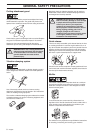
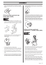
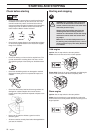
Fitting a blade guard, grass blade
and grass cutter (232R)
• The blade guard (A) is fitted using 4 screws (L) and the
support plate (M) as shown. CAUTION! Always use the
recommended guard for the cutting attachment you are
using. See chapter on Technical data.
• Fit the drive disc (B) on the output shaft.
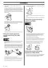
• Turn the blade shaft until one of the holes in the drive disc
aligns with the corresponding hole in the gear housing.
• Insert the locking pin (C) in the hole to lock the shaft.
• Place the blade (D), support cup (E) and support flange
(F) on the output shaft.
• Fit the nut (G). The nut must be tightened to a torque of
35-50 Nm (3.5-5 kpm). Use the socket spanner in the tool
kit. Hold the shaft of the spanner as close to the blade
guard as possible. To tighten the nut, turn the spanner in
the opposite direction to the direction of rotation (Caution!
left-hand thread).
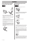
!
WARNING!
When fitting the cutting attachment it is
extremely important that the raised section
on the drive disc/support flange engages
correctly in the centre hole of the cutting
attachment. If the cutting attachment is fitted
incorrectly it can result in serious and/or
fatal personal injury.
!
WARNING! Never use a cutting attachment
without an approved guard. See the chapter
on Technical data. If an incorrect or faulty
guard is fitted this can cause serious
personal injury.
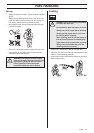
IMPORTANT! If a saw blade or grass blade are to be used
the machine must be equipped with the correct handlebar,
blade guard and harness.
G
F
E
D
B
C
A
L
M