


English – 15
ASSEMBLY
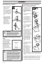
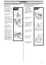
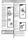
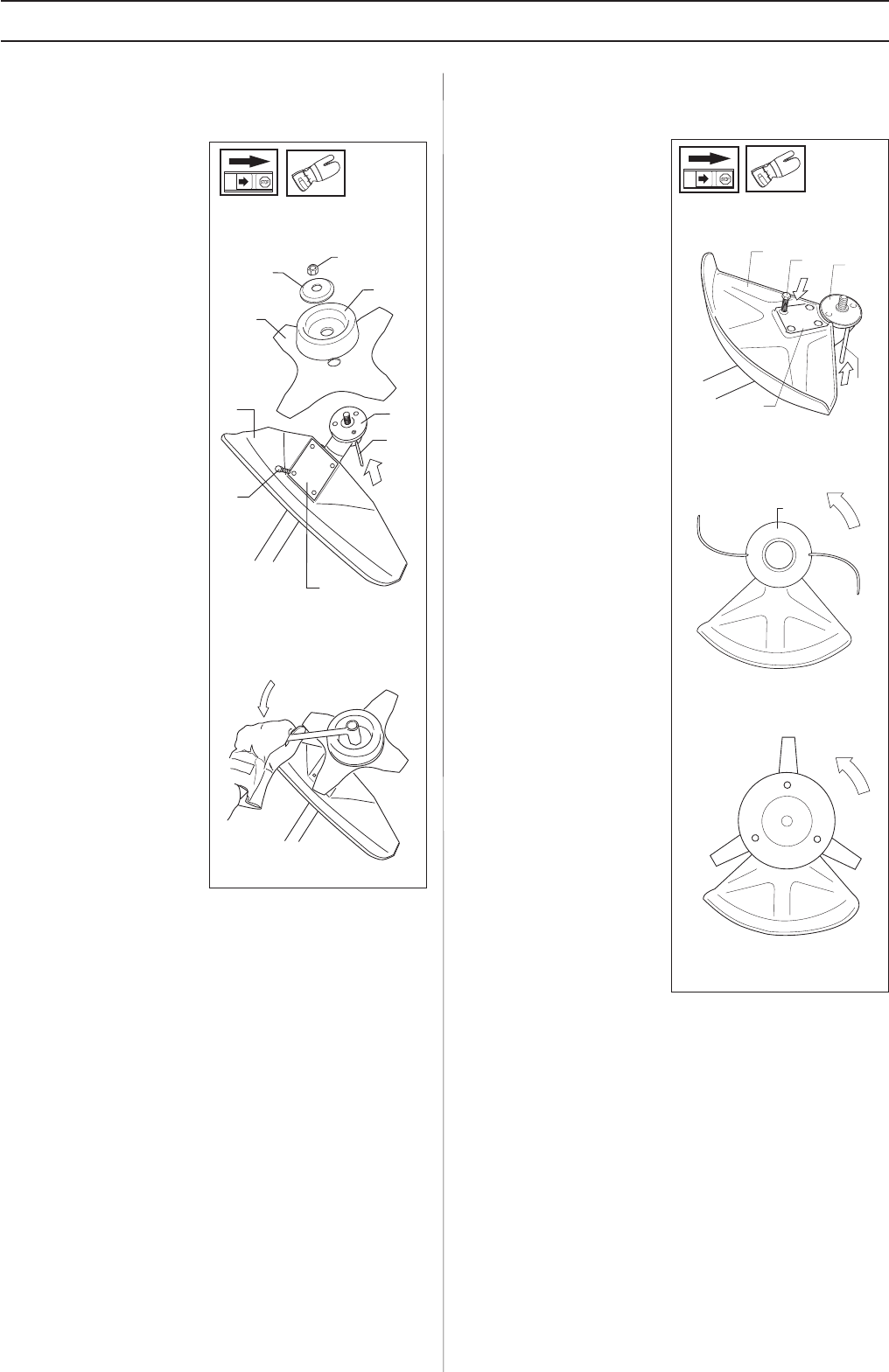
Assembling other guards and
cutting equipment
B
A
L
M
C
H
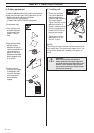
• Fit the guard (A)
intended for use with
the trimmer head.
Secure using four bolts
(L) and the support plate
(M) as shown in the
diagram.
• Fit the disc drive (B) on
the output axle.
• Turn the blade axle until
one of the disc drive’s
holes aligns with the
corresponding hole in
the gear housing.
• Insert the locking pin
(C) into the hole to lock
the axle.
• Screw on the trimmer
head (H) in the
direction of rotation.
• Dismantling takes place
in the reverse order.
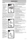
G
F
E
D
B
C
A
L
M
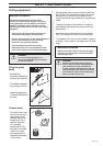
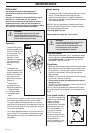
• The guard (A) is fitted
using 4 screws (L) and the
support plate (M) as set
out in the diagram.
NOTE! Use the
recommended blade guard.
• Fit the drive disc (B) on
the output axle.
• Turn the blade axle until
one of the holes in the
drive disc aligns with the
hole in the gear housing.
• Insert the locking pin (C)
in the hole so that the axle
is locked.
• Place the blade (D),
support cup (E) and
support flange (F) on the
output axle.
• Fit the nut (G). The
tightening torque of the
nut is 35-50 Nm (3,5 - 5
kpm). Use the socket
spanner in the tool kit.
Hold the handle of the
spanner as close to the
blade guard as possible.
The nut is tightened when
the spanner is turned
against the direction of
rotation (left-hand thread).
Assembling the blade guard and
grass blade