


English – 13
ASSEMBLY
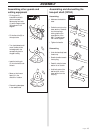
Assembling other guards and
cutting equipment
B
A
L
M
C
H
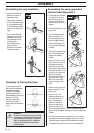
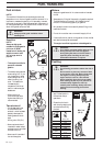
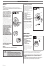
Assembling and dismantling the
two-part shaft (227LD)
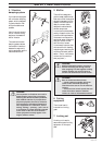
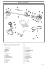
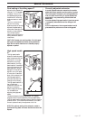
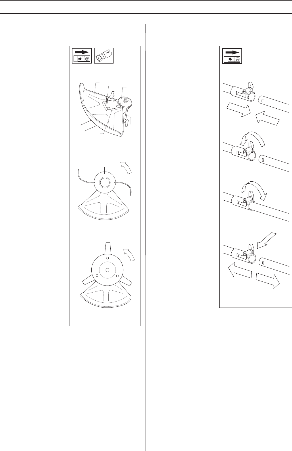
• Fit the guard (A)
intended for use with
the trimmer head.
Secure using four bolts
(L) and the support plate
(M) as shown in the
diagram.
• Fit the disc drive (B) on
the output axle.
• Turn the blade axle until
one of the disc drive’s
holes aligns with the
corresponding hole in
the gear housing.
• Insert the locking pin
(C) into the hole to lock
the axle.
• Screw on the trimmer
head (H) in the
direction of rotation.
• Dismantling takes place
in the reverse order.
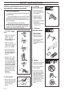
Assembling:
• Make sure the handle is
loose.
• Guide the cut-out on the
lower section of the shaft
into the coupling‘s
locking plate on the
upper section of the
shaft. The sections are
then locked together.
• Tighten the handle.
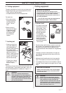
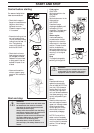
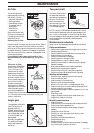
Dismantling
• Undo the handle (at least
three turns).
• Press the handle towards
the coupling.
• Carefully twist the lower
section out of the lock.
• Hold both parts of the
shaft and pull out the
lower section from the
coupling.