


12 – English
ASSEMBLY
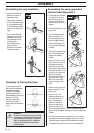
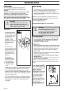
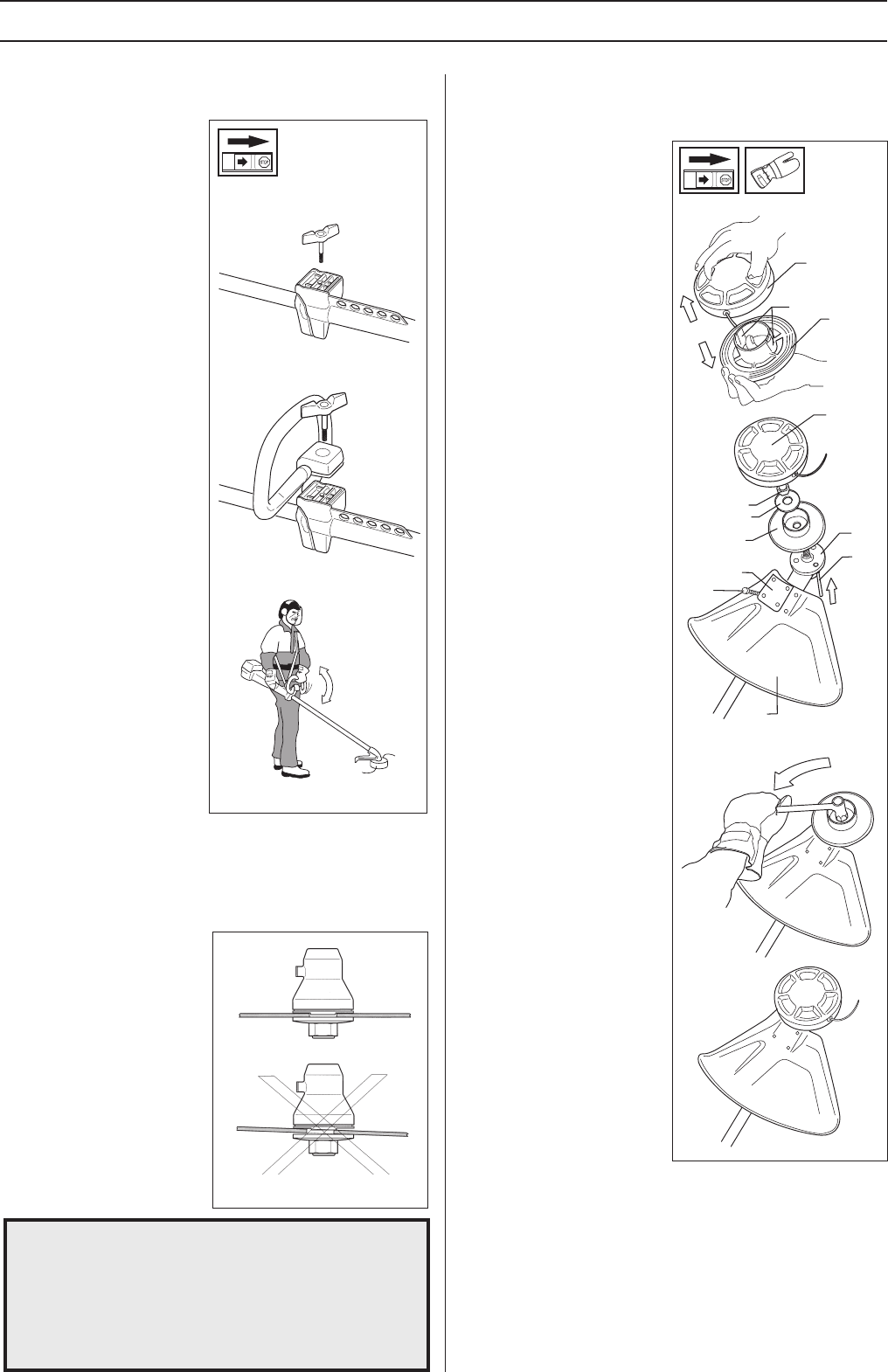
Assembling the loop handlebar
Assembly of the trimmer head
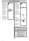
It is extremely important
that the disc drive’s/support
flange’s guide engages
correctly in the cutting
equipment’s centre hole
when assembling the cutting
equipment. Cutting
equipment assembled
incorrectly can result in
serious and/or fatal personal
injury.
!
WARNING!
Under no circumstances may the cutting
equipment be used without an approved
guard fitted. See the chapter
“Technical
data”
. If the wrong guard or a defective
guard is fitted this can cause serious
personal injury.
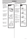
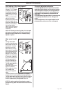
Assembling the spray guard and
trimmer head Superauto II
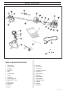
K
J
I
G
F
I
M
L
A
K
B
C
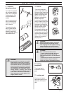
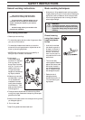
• Unscrew the handle and
plastic cover from the
handlebar bracket.
• Place the loop handlebar
with the handlebar holder
on the handlebar bracket.
Fit the handle and plastic
cover. Do not tighten too
tight.
• Put on the harness and
hang the trimmer in the
suspension hook. Now
finely adjust so that the
trimmer gives a
comfortable working
position when it‘s
attached to the harness.
Tighten the handle.
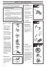
• Fit the guard (A) intended
for use with the trimmer
head. Secure using the 4
bolts (L) and the support
plate (M) as set out in the
diagram.
• Fit the drive disc (B) on the
output axle.
• Turn the blade axle until
one of the holes in the
drive disc aligns with the
hole in the gear housing.
• Insert the locking pin (C)
in the hole so that the axle
is locked.
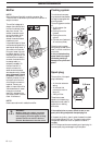
• The trimmer head must be
split to be fitted (see the
diagram). Proceed as
follows:
• Insert your finger into the
centre hole of the cover (I)
at the same time as you
hold the cover with your
other fingers. Press the two
catches (J) that extend from
the cut-out on the bottom
section (K) using the
thumb and index finger of
your other hand. Press
apart the trimmer head
using the fingers on the
cover.
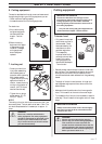
• Place the cover (I) and the
support flange (F) on the
output axle.
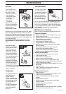
• Fit the nut (G). The
tightening torque of the
nut is 35-50 Nm (3,5-5
kpm). Use the socket
spanner in the tool kit.
Hold the handle of the
spanner as close to the
trimmer guard as possible. The nut is tightened when the
spanner is turned against the direction of rotation (left-hand
thread).
• Fit the trimmer head‘s bottom section (K) on the cover (I)
by pressing the two sections together with the cut-outs on
the bottom section aligned with the catches on the cover.
• To dismantle follow the instructions in the reverse order.