


GASBOY Series 70 & 1820
3-4 9312
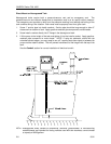
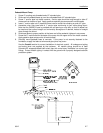
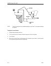
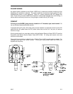
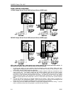
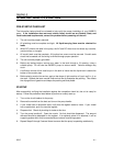
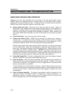
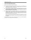
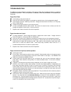
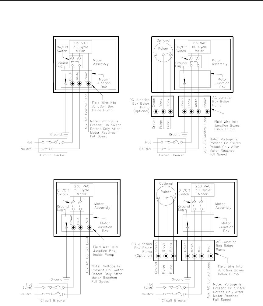
PUMP WIRING DIAGRAMS
115VAC Pumps Series 70 and 1820 (left) and Series 1820R (right)
230VAC Pumps Series 70 and 1820 (left) and Series 1820R (right)
NOTE FOR 230V MOTORS: Some motors may contain different wire colors than those shown. In
this case, Hot is Black, Neutral is White and Aux AC Control is Brown.
1. All wiring and conduit runs must conform with all building/fire codes, all Federal, State, and Local
codes, National Electrical Code, (NFPA 70), NFPA 30, Automotive and Marine Service Station Code
(NFPA 30A), and NFPA 395 codes and regulations.
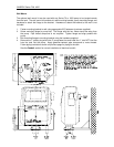
2. For the Series 70 and Series 1820 rounded cabinet models, make the field wire connections in the
motor junction box. The 1820R models with the squared cabinet come with the wires already
extended through the end of a factory-installed conduit. The 1820R models also come with a junction
box which is to be mounted directly beneath the pump. The field wire connections for the 1820R
models should be made in this junction box (not the pump motor junction box). Wire connections
should be tightly spliced and secured with a wire nut. Close off the end of the wire nut with electrical
tape.
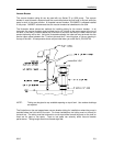
3. The Aux AC Control Lead wire is shipped capped from the factory. When used, it connects to a
solenoid valve or fuel management system. Do not connect this wire without first checking the ON
voltage of this line to ascertain compatibility with the equipment being connected.
4. Pulser wiring must be 18AWG and installed in metal conduit separate from all AC wiring. It cannot
share a common junction box, wiring trough or conduit with any AC wiring.