


9
42606-01 • 06/27/11 • Hunter Fan Company
All wiring must be in accordance with national and local electrical
codes and ANSI/NFPA 70. If you are unfamiliar with wiring, use a
qualified electrician.
Wall switches are not included. Select an acceptable general-use switch
in accordance with national and local electrical codes.
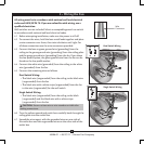
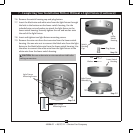
4.1 Before attempting installation, make sure the power is still o.
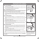
4.2 To connect the wires, hold the bare metal leads together and place
a wire connector over them, then twist clockwise until tight. For
all these connections use the wire connectors provided.
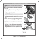
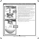
4.3 Connect the bare or green ground wire (grounding) from the
ceiling to the green ground wire (grounding) from the ceiling plate
and the green ground wire (grounding) from the fan. If you chose
the low prole option, the green ground wire from the fan can be
found on the low prole washer.
4.4 Connect the white wire (grounded) from the ceiling to the white
wire (grounded) from the fan.
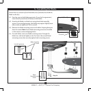
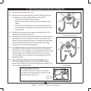
4.5 Connect the remaining wires as follows:
Dual Switch Wiring:
• e black wire (ungrounded) from the ceiling to the black wire
(ungrounded) from the fan
• e black wire with a white stripe (ungrounded) from the fan
to the wire (ungrounded) for the wall switch
Single Switch Wiring:
• e black wire (ungrounded) from the ceiling to the black
(ungrounded) and the black wire with a white stripe
(ungrounded) from the fan
CAUTION: Be sure no bare wire or wire strands are visible after
making connections.
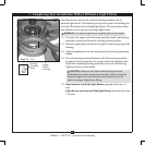
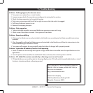
4.6 Turn the splices upward and push them carefully back through the
ceiling plate into the outlet box.
4.7 Spread the wires apart, with the grounded wires on one side of
the outlet box and the ungrounded wires on the other side of the
outlet box.
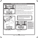
Dual Switch Wiring
Single Switch Wiring
Wire
Connector
4 • Wiring the Fan