


12
42221-01 • 06/04/12 • Hunter Fan Company
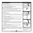
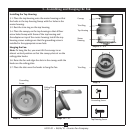
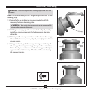
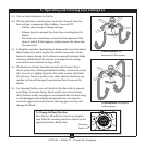
Steps 7-1 – 7-4
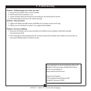
Step 7-5
Switch Housing
Screw
Switch Housing
Screw
Upper
Switch
Housing
Mounting
Plate
WARNING: Use only the light xture supplied with this fan model.
7-1. To attach the upper switch housing, partially install two
switch housing screws into the mounting plate.
7-2. Feed the upper plug connector through the center opening
of the housing.
7-3. Align the keyhole slots in the housing with the switch
housing screws.
7-4. Turn the housing counterclockwise until the housing
assembly screws are rmly situated in the narrow end of the
keyhole slots. Install the remaining screw into the housing.
Tighten all three screws rmly.
CAUTION: Make sure the upper switch housing is securely
attached to the switch housing mounting plate. Failure to
properly attach and tighten all three assembly screws could
result in the switch housing and light xture falling.
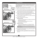
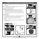
7-5. To attach the lower switch housing, partially install three
stando screws into the standos as shown, leaving the
circled stando empty.
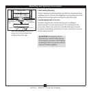
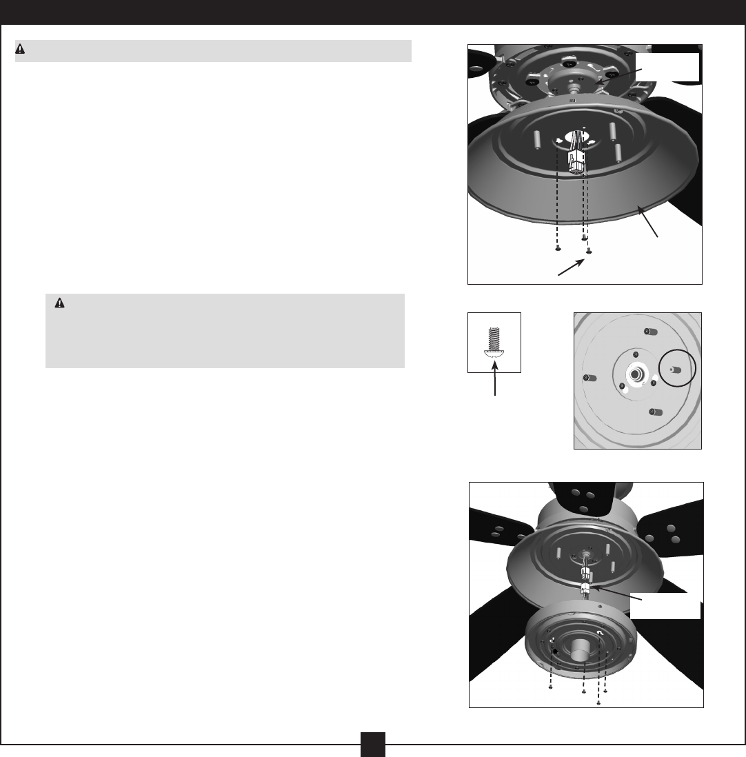
7-6. To attach the lower switch housing, connect the upper plug
connector from the motor to the lower plug connector in
the lower switch housing assembly.
Note: Both plug connectors are polarized and will only t
together one way. Make sure the connectors are properly
aligned before connecting them. Incorrect connection could
cause improper operation and damage to the product.
7-7. Align the keyhole slots in the lower switch housing with the
stand o screws.
7-8. Turn the housing counterclockwise until the stando screws
are rmly situated in the narrow end of the keyhole slots.
Install the remaining screw into the housing. Tighten all four
screws rmly.
Steps 7-6 – 7-8
Plug
Connector
7 • Completing Your Installation With a Bowl Light Fixture