


ELECTRICAL DIAGNOSTICS (ALL MODELS EXCEPT HW3000/L)
8-6 www.honeywellgenerators.com Honeywell Portable Electrical Generator Service Manual
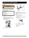
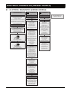
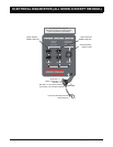
8.2 ELECTRICAL DIAGNOSTICS (ALL MODELS EXCEPT HW3000/L)
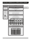
Perform “Alternator Check”
Check for Tripped Master Breaker
Resolve Overload Problem to Ensure Safe Operation
After Electrical Load Resolved Push to Reset Breaker
If Cannot Reset, Replace Breaker
Check for Tripped Duplex Circuit Breaker(s)
Outlets Above the Breaker Indicate
the Excess Load Source
Resolve Overload Problem to Ensure Safe Operation
After Electrical Load Resolved Wait Several Minutes
(for Thermal Breaker to Cool) Push to Reset Breaker
If Cannot Reset, Replace Breaker
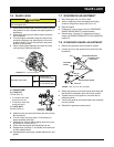
Start Engine and Run at No Load
Check Engine Frequency = 61.5 to 63 Hz
Adjust Governor, if necessary
(see Manual Section “Governor Adjustment”)
If Frequency Still Out of Range,
see
Engine Diagnostics Section
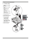
Check Voltage Output at
NEMA L14-30R 240V Receptacle
G
Y
W
X
123-
126V
246-
252V
123-
126V
If Voltage Out of Range, Perform “240V Circuit Check”
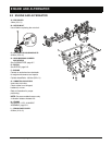
W
G
X
123-
126V
Check Voltage Output at NEMA 5-20R 120V
Duplex Outlet #1
If Voltage Out of Range, Perform “120V Circuit Check”
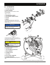
W
G
Y
123-
126V
Check Voltage Output at NEMA 5-20R 120V
Duplex Outlet #2
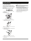
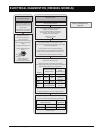
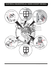
Remove Alternator End Cover
240V Circuit Check
(No Output OR
Voltage Out of Spec)
Check Wires and Connections
from AVR to Brush Assembly
for Proper Orientation
of Wire Connections
If a Connection is Loose or
Disconnected, Reestablish
a Tight Connection
If a Wire or Connection is Damaged,
Replace AVR
Check for Continuity in Each Circuit
of the 240V Receptacle
from the Female Socket on the Front
to the Terminal on the Back
If No Continuity,
Replace Duplex Receptacle
If Continuity Present,
Replace Electrical Panel
Check Continuity from the
120V Duplex Receptacle
for Each Connection (X or Y, W, G)
to the 240V Receptacle
If Continuity Not Present
in Any Circuit,
Check Wires and Connections from
120V Duplex to 240V Receptacle
If a Connection is Loose or
Disconnected, Reestablish a
Tight Connection and Recheck
Continuity
If a Wire or Connection
is Damaged,
Replace Electrical Panel
120V Circuit Check
(No Output OR
Voltage Out of Spec)
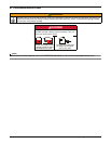
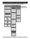
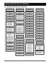
General Electrical Check
Check Output Voltage (X to Y) of the
240V Receptacle = 246-252V
Adjust Voltage Regulator, if Necessary
by Turning the Potentiometer on
the Rear of the Voltage Regulator
If Voltage Still Out of Range
Replace Voltage Regulator
If Voltage Out of Range, Perform “120V Circuit Check”
Conduct This Check Only When
Directed by General Electrical Check
Start Engine and Run at No Load
Conduct This Check Only When
Directed by General Electrical Check
Check for Continuity in
Each Leg of Master Breaker
from the Line Terminal
to the Load Terminal
If No Continuity,
Replace Master Circuit Breaker
Check for Continuity in
Duplex Breaker
from the Line Terminal
to the Load Terminal
If No Continuity,
Replace Duplex Circuit Breaker
Check for Continuity in
Each Circuit of the
120V Duplex Receptacle from
the Female Socket on the Front
to the Terminal on the Back
If No Continuity,
Replace Duplex Receptacle
If Continuity Present,
Replace Electrical Panel
Remove Main Control Panel from
Control Panel Assembly
Check Wires and Connections
for the Exciter & AVR Tap
from AVR to Alternator
On AVR Side of Connection:
If a Connection is Loose or
Disconnected, Reestablish a
Tight Connection
If a Wire or Connector is Damaged,
Replace AVR
On Alternator Side of Connection:
If a Connection is Loose or
Disconnected, Reestablish a
Tight Connection
If a Wire or Connector
is Damaged,
Replace Alternator
Check for Continuity from
the 240V Receptacle
for Each Connection (X, Y, W, G) to
Corresponding Alternator Terminal
If Continuity Not Present
in Any Circuit,
Check Wires and Connections
from Receptacle to Alternator
If a Connection is Loose or
Disconnected, Reestablish a Tight
Connection and Recheck Continuity
If a Wire or Connection is Damaged,
Replace Electrical Panel
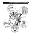
Refer to Illustrations on
Pages 8-7 and 8-9.