


HW7000EH Portable Electrical Generator Owner’s Manual www.honeywellgenerators.com 13
COMPONENTS
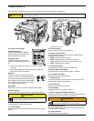
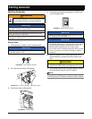
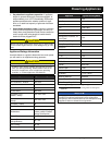
Use information provided in this section to become familiar with your generator’s components.
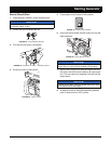
A—Power Control Center
Household Outlets
125VAC 20 Amp Duplex (NEMA 5-
20R) outlets to connect 120V appli-
ances to generator for power.
Generator Cord
125/250VAC 30 Amp Twist-Lock
(NEMA L14-30R) outlet can be used
to:
• Power 120V appliances using 4-in-1 power cord (not
included).
• Power 240V appliances using appropriate (NEMA L14-
30P) power cord (not included).
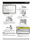
Breakers
Protects circuits from damage caused by
overload or short-circuit by stopping the flow
of electricity from the generator to the appli-
ance. Master circuit breaker controls power
to all outlets. If there is no power at outlets,
see Troubleshooting section.
Hour Meter
Shows the total unit run time for maintenance purposes.
Ground Terminal
Connects generator to ground wire for grounding protection.
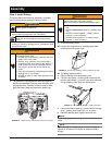
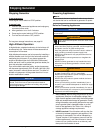
B—Battery Tray and Battery
Provides power for electric start feature.
C—Oil Fill Dipstick
Seals off engine oil fill hole and provides indicator for engine
oil level.
D—Oil Drain Screw
Allows engine oil to drain from generator.
E—Engine Control Switch
Control used to start and stop the engine. Engine control
switch has three positions:
• START—Starts generator engine
• RUN—Prepares engine to start (manual start);
Indicates engine is currently running (electric start)
• STOP—Stops generator engine
F—Fuel Shut-off Valve
Controls flow of fuel from fuel tank to carburetor.
G—Recoil Starter Grip Handle
Provides means to manually start engine, if needed.
H—Air Cleaner Assembly
Removes dust from engine intake air.
I— Choke Control
Controls choke valve. Choke control must be moved to ON
position when starting a cold engine.
J—Fuel Tank Cap
Provides a secure seal on fuel tank.
K—Fuel Gauge
Indicates level of fuel currently in fuel tank.
L—Muffler Equipped with Spark Arrestor
Provides outlet for engine exhaust. Prevents sparks and other
combustible materials from escaping generator.
M—Spark Plug Cap (Wire)
Delivers voltage to spark plug. When spark plug needs ser-
vice, cap must be removed.
N—Carbon Canister
Reduces hydrocarbon emissions.
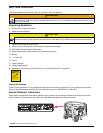
The information below is provided for reference only. Refer to “OPERATION” on page 15 for instructions
on operating the generator.
FIGURE 19: HW7000EH Portable Electrical Generator
CAUTION
J
G
B
I
H
K
E
C
D
A
F
M
L
N
Generator must be grounded to prevent electrical
shock from faulty appliances. See page 11.
Set
Tripped
CAUTION
Muffler reaches temperatures that can cause serious
burns if touched. NEVER touch hot surfaces.
WARNING