


Honeywell Portable Electrical Generator Service Manual www.honeywellgenerators.com 7-7
VALVE LASH
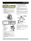
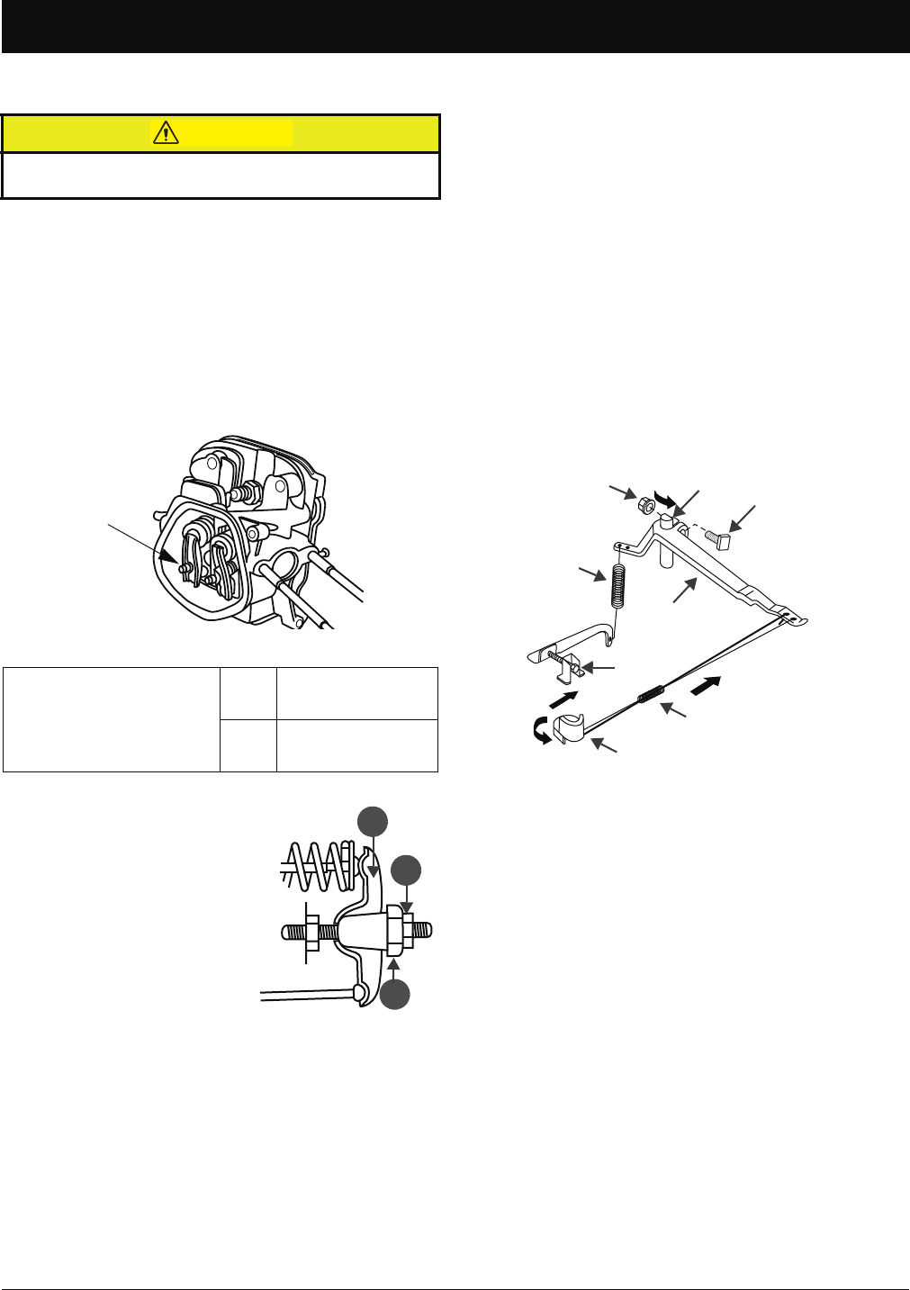
7.6 VALVE LASH
1. Remove the cylinder head cover and carefully remove
the gasket for re-use. (Inspect and replace gasket, if
necessary.)
2. Remove the spark plug to reduce engine compres-
sion resistance.
3. Turn the engine crankshaft using the recoil starter,
positioning engine at top, dead center, of the com-
pression stroke. This can be verified by the piston
position in the cylinder.
4. Insert a feeler gauge between the rocker arm and
valve spring to measure valve lash.
5. Hold the rocker arm pivot and loosen the lock nut (see
B in illustration).
6. Turn the rocker arm pivot (see C in illustration) to
obtain specified valve lash.
7. Retighten the lock nut while holding rocker arm pivot
and torque to 12 N•m (9 lb. ft.).
8. Check valve lash again after tightening lock nut.
9. Repeat steps 4 through 7, as needed, until valve lash
is within specifications.
10. Reassemble the spark plug, cylinder head cover, and
gasket.
7.7 GOVERNOR ADJUSTMENT
1. Start the engine and run with no load.
2. Attach a frequency meter and adjust the limiting
screw on the governor stop to 62.5 Hz ± 0.5.
3. Stop the engine.
4. If frequency is out of range, see the “GOVERNOR
RANGE ADJUSTMENT” procedure below.
5. Repeat steps 1 through 3. If frequency still out of
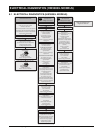
range, see ENGINE DIAGNOSTICS (ALL MODELS),
page 8-10
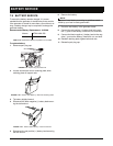
7.8 GOVERNOR RANGE ADJUSTMENT
1. Remove the generator control panel for access.
2. Loosen the nut on the governor arm pinch bolt (see
illustration).
3. Rotate the governor arm shaft counter-clockwise until
the throttle is completely open and hold in position.
4. Tighten the nut on the governor arm pinch bolt to
maintain position.
5. Confirm the governor arm and throttle move smoothly
and do not bind.
6. Reinstall the generator control panel.
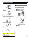
Valve lash inspection and adjustment must be performed
with the engine cold.
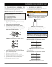
FIGURE 7-17: Lock Nut Location
Standard valve lash
IN.
0.005±0.001 in
(0.125±0.025 mm)
EX.
0.007±0.001 in
(0.175±0.025 mm)
TABLE 7-5. Standard Valve Lash
A—ROCKER ARM
B—LOCK NUT
12 N•m (9 lb. ft.)
• To increase valve lash,
screw pivot nut out.
• To decrease valve lash,
screw pivot nut in.
C—PIVOT BOLT
30 N•m (22 lb. ft.)
CAUTION
LOCK NUT
A
B
C
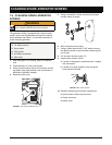
FIGURE 7-18: Governor Arm Assembly
GOVERNOR ARM SHAFT
GOVERNOR ARM
PINCH BOLT
GOVERNOR ARM
ANTI-SURGE SPRING
THROTTLE
NUT
GOVERNOR
SPRING
LIMITING
SCREW