


Page 8 — English
NOTE: This tool is heavy. To avoid back injury, lift with
your legs, not your back, and get help when needed.
Inspect the tool carefully to make sure no breakage or
damage occurred during shipping.
Do not discard the packing material until you have care-
fully inspected and satisfactorily operated the tool.
If any parts are damaged or missing, please call
1-800-242-4672 for assistance.
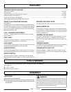
PACKING LIST
Pressure Washer
25 ft. High Pressure Hose
Trigger Handle Holder
Trigger Handle
Screw (1/4-20 x 1.65 in., Pan Hd.)
Screw (1/4-20 x 1.85 in. Pan Hd.)
Screw (1/4-20 x 2.27 in. Pan Hd.)
Spray Wand
5-in-1 Change Over Nozzle
Injection Hose plus Filter
Flat Washer
4-Cycle Engine Lubricant (SAE 30 or SAE 10W30)
Hose Storage
Operator’s Manual
WARNING:
If any parts are damaged or missing do not operate this
product until the parts are replaced. Use of this product
with damaged or missing parts could r esult in serious
personal injury.
WARNING:
Do not attempt to modify this product or create acces-
sories not recommended for use with this pr oduct. Any
such alteration or modification is misuse and could result
in a hazardous condition leading to possible serious
personal injury.
WARNING:
To prevent accidental starting that could cause serious
personal injury, always disconnect the engine spark plug
wire from the spark plug when assembling parts.
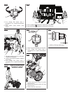
RAISING AND LOWERING THE HANDLE
See Figure 2.
To raise the handle (for moving the pressure washer): pull
the handle up until the handle release knob snaps into
locking position. Ensure the lock is secured in the frame
hole before moving.
To lower the handle (for storing or transporting the pres-
sure washer): pull the handle release knob out and lower
the handle to the down position.
NOTE: The handle can not be locked in the down posi-
tion.
Never use the handle to lift the pressure washer. The handle
should only be used for moving the unit by r olling it on its
wheels.
INSTALLING HOSE STORAGE, TRIGGER
HANDLE HOLDER, AND SPRAY WAND HOLDER
See Figures 3 - 4.
Raise handle as described in the Raising and Lowering
Handle section.
Place hose storage onto the handle as shown.
Align the holes in the hose storage with the holes in the
handle.
Insert bolt (1/4-20 x 1.65 in.) through the holes in the left
side of the handle and hose storage.
Place nut onto bolt and tighten.
Place the trigger handle holder onto the handle as shown.
Align the holes in the trigger handle holder with the holes
in the hose storage and the handle.
Insert bolt (1/4-20 x 2.27 in.) through the holes in handle,
hose storage, and trigger handle holder.
Turn bolt while holding the nut in place to tighten and
secure.
Place spray wand holder onto pressure washer frame.
Align the holes in the spray wand holder with the holes
in the pressure washer frame.
Insert screw (1/4-20 x 1.85 in.) through the holes in the
spray wand holder and the pressure washer frame.
Place nut onto screw and tighten.
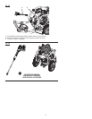
ASSEMBLING THE SPRAY WAND TO THE
TRIGGER HANDLE
See Figure 5.
Place the threaded end of the spray wand in the connector
on the end of the trigger handle.
Turn the connector clockwise until it stops. This secures
the spray wand in place.
ASSEMBLY