


Page 8 — English
ASSEMBLY
PACKING LIST
Pressure Washer
25 ft. High Pressure Hose
Trigger Handle
Spray Wand
Quick-connect Nozzles (4)
Injection Hose
Injection Hose Filter
Upper Spray Wand Holder
Lower Spray Wand Holder
Lock Nut
M8 10 mm Bolt
M8 13 mm Flange Nut
4-Cycle Engine Lubricant (SAE 30 or SAE 10W30))
Axle (2)
Hitch pins (2)
Wheels (2)
Washers (2)
Handle
Operator’s Manual
TOOLS NEEDED
See Figure 1a.
13 mm Socket Wrench (9/16 in.)
10 mm Wrench (7/16 in.)
WARNING:
If any parts are damaged or missing do not operate this
tool until the parts are replaced. Use of this product
with damaged or missing parts could result in serious
personal injury.
WARNING:
Do not attempt to modify this tool or create accesso-
ries not recommended for use with this tool. Any such
alteration or modification is misuse and could result in a
hazardous condition leading to possible serious personal
injury.
WARNING:
To prevent accidental starting that could cause serious
personal injury, always disconnect the engine spark plug
wire from the spark plug when assembling parts.
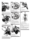
ATTACHING THE WHEEL ASSEMBLY
See Figure 2.
Locate the axle, hitch pins, washers, and wheels.
Slide the axle through the hole in the center of the
wheel.
Slide the washer onto the axle.
Lift the machine and slide the axle into the wheel mount-
ing hole in the machine base as shown.
Push the hitch pin into the hole on the end of the axle to
secure the wheel assembly.
NOTE: The hitch pin should be pushed into the axle until
the center of the pin rests on top of the axle.
Repeat with the second wheel.
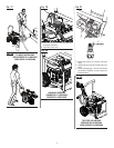
INSTALLING THE HANDLE
See Figure 3.
Push and hold the push-pin button on the side of the handle
as you slide the handle onto the frame.
NOTE: Before use, pull the handle up until the lock
button snaps through the locking slots to secure the handle
in place.
INSTALLING THE UPPER AND LOWER
SPRAY WAND HOLDER
See Figure 4.
Align upper spray wand holder with holes in handle, as
shown.
Slide long side of spray wand holder through handle and
tighten securely with lock nut.
Place lower spray wand holder over the holes.
Align the bolt with the holes and push the bolt through.
Hold flange nut with 13 mm wrench and bolt head with
10 mm socket. Tighten until the bolt is snug.
ASSEMBLING THE TRIGGER HANDLE
See Figure 5.
Place the threaded end of the spray wand in the connector
on the end of the trigger handle.
Turn the connector clockwise until it stops. This secures
the spray wand in place.
CONNECTING HIGH PRESSURE HOSE TO
TRIGGER HANDLE
See Figure 6.
Screw the collar on the high pressure hose into the
trigger handle inlet coupler by turning the hose collar
clockwise.
Pull on the hose to be certain it is properly secured.
ATTACHING INJECTION HOSE
See Figure 7.
Before detergent can be used with this machine, the injection
hose must be attached.
Push the injection hose filter onto the end of the injection
hose (if not already installed).
Push the open end of the clear injection hose securely
over the fitting.
NOTE: Keep injection hose away from hot surfaces.