


Page 8
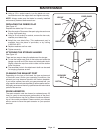
FEATURES
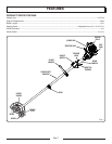
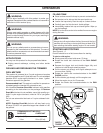
KNOW YOUR EDGER
See Figure 1.
The safe use of this product requires an understanding of
the information on the tool and in this operator’s manual as
well as a knowledge of the project you are attempting. Before
use of this product, familiarize yourself with all operating
features and safety rules.
TOP-MOUNTED MOTOR
The top-mounted motor improves balance and is located
away from the dust and debris of the cutting area.
ASSEMBLY
UNPACKING
This product requires assembly.
Carefully remove the product and any accessories from
the box. Make sure that all items listed in the packing list
are included.
Inspect the product carefully to make sure no breakage
or damage occurred during shipping.
Do not discard the packing material until you have care-
fully inspected and satisfactorily operated the product.
If any parts are damaged or missing, please call
1-800-242-4672 for assistance.
PACKING LIST
Edger Assembly
Handle Assembly
Holding Pin
Hanger Cap
Bottle of 2-Cycle Lubricant
Operator’s Manual
WARNING:
If any parts are damaged or missing, do not operate this
product until the parts are replaced. Failure to heed this
warning could result in serious personal injury.
WARNING:
Do not attempt to modify this product or create acces-
sories not recommended for use with this product. Any
such alteration or modification is misuse and could result
in a hazardous condition leading to possible serious
personal injury.
WARNING:
To prevent accidental starting that could cause serious
personal injury, always disconnect the engine spark plug
wire from the spark plug when assembling parts.
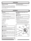
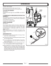
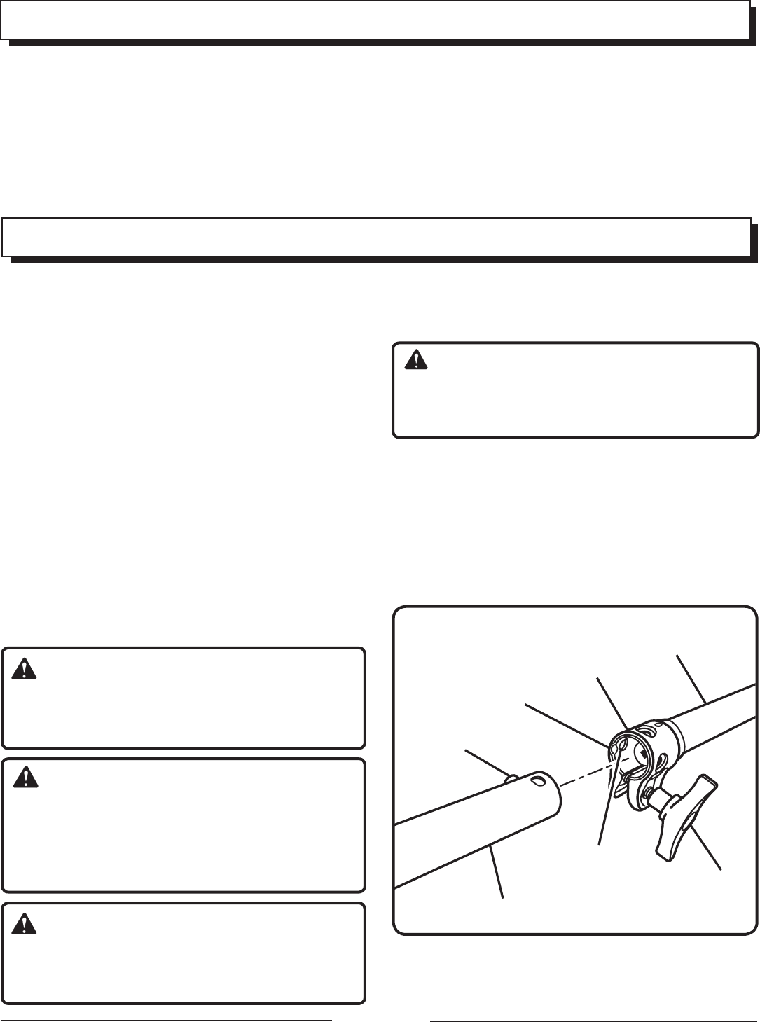
INSTALLING THE POWER HEAD TO THE
ATTACHMENT
See Figure 2.
WARNING:
Never install, remove, or adjust any attachment while
power head is running. Failure to stop the engine can
cause serious personal injury.
The attachment connects to the power head by means of
a coupler device.
Loosen the knob on the coupler of the power head shaft
and remove the end cap from the attachment.
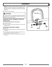
Push in the button located on the attachment shaft. Align
the button with the guide recess on the power head coupler
and slide the two shafts together. Rotate the attachment
shaft until the button locks into the positioning hole.
Fig. 2
cOUPLER
kNOB
ATTAcHMENT SHAFT
POSITIONING
HOLE
GUIDE
REcESS
BUTTON
POwER HEAD
SHAFT