


3
5.0 RECOMMENDED OPERATING
PROCEDURES
Ignite the fire in the fireplace with the variable speed control
switch in an "ON" position. The fan will automatically turn
on when the temperature sensor switch closes at approxi-
mately 110
O
F. Heated air should be delivered at the outlet
grille. The fan will continue to operate after the fireplace is
turned OFF until the sensor switch opens.
Various conditions (such as fireplace model, type of fire-
place installation, outside air temperature vs. inside air tem-
perature) can contribute to the length of the time the blower
remains on after the fireplace is turned OFF. The blower can
be turned off manually with the speed control switch.
WARNING: NEVER CONTACT BLOWER WHEEL (VANES)
DURING BLOWER OPERATION.
6.0 MAINTENANCE
Periodically check the fireplace grilles and remove any dust,
dirt or obstructions.
7.0 REPLACEMENT PARTS AND CUSTOMER
SERVICE
Replacement parts and service may be obtained through
your dealer.
Hardware Bag: SRV107-570A
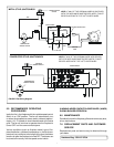
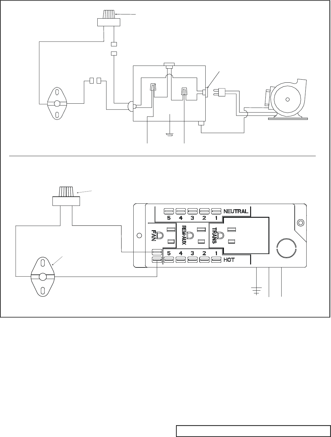
FIGURE 5 Fan Wiring Diagram
NOTE: IF ANY OF THE ORIGINAL WIRE AS SUPPLIED
WITH THE APPLIANCE MUST BE REPLACED, IT MUST
BE REPLACED WITH TYPE 105
O
C RATED WIRE.
BLOWER
BLOWER RECEPTACLE
BLK
WHT
WHT
GROUND
GRN
110-120 VAC
WHT
BLK
BLK
JUNCTION BOX
BLK
TEMPERATURE
SENSOR SWITCH
BLK
BLK
BLK
BLK
VARIABLE SPEED
SWITCH
GROUND
WIRE
METAL STYLE JUNCTION BOX
POWER STRIP STYLE JUNCTION BOX
BLUE
VARIABLE
SPEED SWITCH
TEMPERATURE
SENSOR SWITCH
JUNCTION BOX
NOTE: IF ANY OF THE ORIGINAL WIRE AS SUPPLIED
WITH THE APPLIANCE MUST BE REPLACED, IT MUST
BE REPLACED WITH TYPE 105
O
C RATED WIRE.