


2
4.2 INSTALLING THE BLOWER
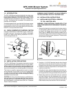
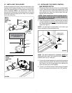
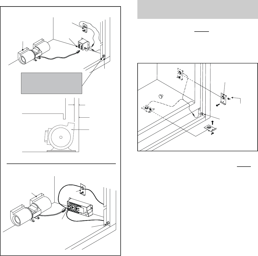
Position the blower all the way to the rear and center in the
fireplace. Pull the blower forward 1/8" to 1/4" from the back
wall of the fireplace (Figure 3). Plug the blower cord into the
blower receptacle FAN on the junction box. Attach the
ground wire to the bottom of the junction box or to a good
accessible metal grounded source. Note: You can attach
this to the firebox leg.
FIGURE 3
BLOWER
“FAN”
RECEPTACLE
SPEED
CONTROL
SENSOR
SWITCH
NOTE: SOME MODELS MAY HAVE
A SEPARATE MOUNTING LOCATION
ON THE BASE PAN OR VALVE
BRACKET FOR MOUNTING THIS
SPEED CONTROL
FIREPLACE
WALL
BLOWER
1/8” TO 1/4”
BLOWER
SENSOR
SWITCH
“FAN”
RECEPTACLE
SPEED
CONTROL
METAL
STYLE
JUNCTION
BOX
POWER STRIP
STYLE
JUNCTION
BOX
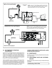
4.3 INSTALLING THE SPEED CONTROL
AND SENSOR SWITCH
1. Remove the knob and locknut from the variable speed
control. Slide the control behind the fireplace wall, in the
lower right front corner, with the stem sticking out of the
pre-punched hole. Attach the locknut tightly and reat-
tach the knob on the stem.
NOTE: Some models may have a separate mount-
ing location on the base pan or valve bracket for
mounting this speed control.
2. Slide the temperature sensor switch/bracket assembly
onto the weld stud on the outside of the combustion cham-
ber. Secure the bracket assembly with the wing nut pro-
vided. See Figure 4.
NOTE: The weld stud is located either on the lower right
side or the bottom of the combustion box.
NOTE: THE SWITCH/BRACKET ASSEMBLY MUST BE
INSTALLED SO THAT THE SENSOR SWITCH IS TO-
WARDS THE TOP OF THE UNIT.
3. Connect the variable speed control and the temperature
sensor switch to the junction box with the wires provided.
See Figure 5 for the wiring diagram that matches the
style of junction box on the fireplace.
4. Turn the 110-120 VAC service "ON" at the circuit breaker
and turn the speed control switch to the "ON" position.
WING
NUT
TEMPERATURE
SENSOR SWITCH
SPEED
CONTROL
FIGURE 4