


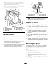
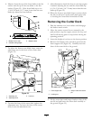
5. Slide the rubber cover up the positive (red) cable.
Disconnect the positive (red) cable from the battery
post (Figure 41). Retain all fasteners.
6. Remove the battery hold-down (Figure 41) and lift
the battery from the battery tray.
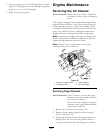
G005072
1
2
3
4
5
6
7
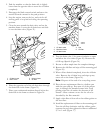
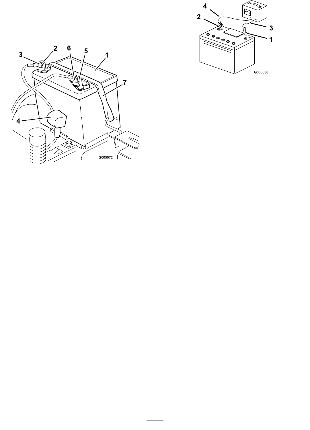
Figure 41
1. Battery 5. Negative battery post
2. Positive battery post 6. Wing nut, washer, and bolt
3. Bolt, washer, and nut 7. Battery hold-down
4. Terminal boot
Charging the Battery
Service Interval: Before storage—Charge the battery
and disconnect battery cables.
1. Remove the battery from the chassis; refer to
Removing the Battery.
2. Charge the battery for a minimum of 1 hour at 6 to
10 amps. Do not overcharge the battery.
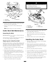
3. When the battery is fully charged, unplug the charger
from the electrical outlet, then disconnect the
charger leads from the battery posts (Figure 42).
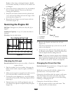
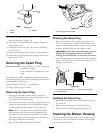
Figure 42
1. Positive battery post
3. Red (+) charger lead
2. Negative battery post
4. Black (-) charger lead
Note: Do not run the machine with the battery
disconnected, electrical damage may occur.
Installing the Battery
1. Position the battery in the tray with the terminal
posts toward the operating position (Figure 41).
2. Install the positive (red) battery cable to the positive
(+) battery terminal using the fasteners removed
previously.
3. Install the negative battery cable to the negative
(-) battery terminal using the fasteners removed
previously.
4. Slide the red terminal boot onto the positive (red)
battery post.
5. Secure the battery with the hold-down (Figure 41).
6. Install the left side console. Refer to the Accessing
the Battery procedure in Premaintenance Procedures
for instructions.
Servicing the Fuses
The electrical system is protected by fuses. It requires
no maintenance; however, if a fuse blows, check the
component/circuit for a malfunction or short.
Fuse:
• Main F1-30 amp, blade-type
• Charge Circuit F2-25 amp, blade-type
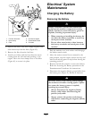
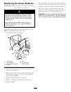
1. Raise the seat to gain access to the fuse holder
(Figure 43).
2. To replace a fuse, pull out on the fuse to remove it
(Figure 43).
34