English – 7
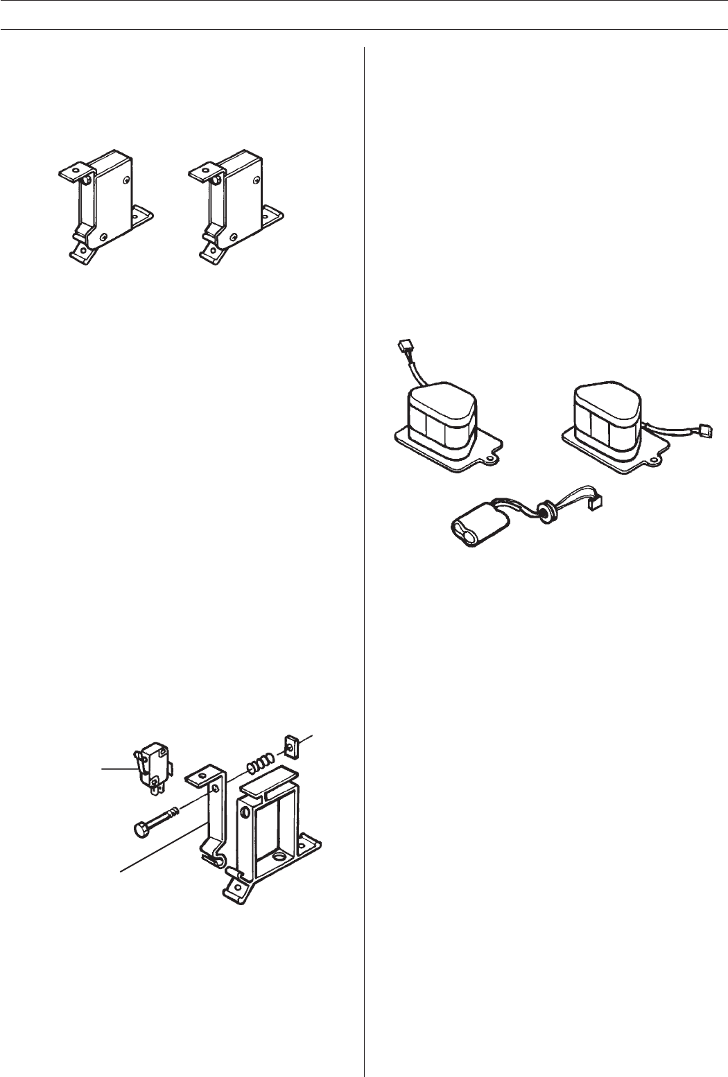
Microswitches (Collision detectors)
The front panel’s rear edge is suspended in two, spring-loaded
aluminium levers.
These levers in turn activate two microswitches which are
integrated in the “housings“ (see the diagram below) that
connect the front panel with the box.
TROUBLE SHOOTING
The batteries are used in the lawn mower to power the “compu-
ter“, i.e. the circuitboard with microprocessor, even at night to
ensure that the theft alarm works. The batteries also act as a
buffer when the lawn mower is mowing in the shade or during a
cloudy or a partially sunny day. This is why the lawn mower can
still mow for short periods on cloudy days.
In the generator, the battery ensures that the loop is generating
an electromagnetic field even when the sun is not shining
sufficiently to power the generator. It is important that the
generator is placed where it is well lit.
If the lawn mower requires long charging times on very sunny
days and, despite this, only has a short operating time, it’s
reasonable to suspect that the batteries need to be replaced.
The batteries in the lawn mower should be changed in pairs to
guarantee operations, as a new battery with a relatively old
battery will reduce capacity and in some cases completely
destroy the new battery. If changing the batteries does not help,
check whether the solar panels are functioning correctly.
Another sign that the batteries are discharged is when the lawn
mover frequently stops in the shade to charge.
If the lawn mower has difficulties in sensing the electromagnetic
field from the loop cable when it’s cloudy, at daybreak or dusk,
the battery in the generator may need to be replaced, see page
2. Thereafter check that the cables outside and inside the
generator are in working order, and that there are no loose
connections.
The lawn mower stands in the charging mode (2 beeps/10
seconds) for a maximum of 40 minutes, irrespective of whether
the batteries are fully charged or not.
Batteries
Two, series connected 6V Nickel-Cadmium batteries are used
in the lawn mower. One, 2.4V Nickel-Cadmium battery is used
in the generator.
Cables
The cables are used to connect all the electrical components on
the lawn mower that concern, propulsion, charging, communica-
tion and mowing.
When checking whether a cable break has occurred all connec-
tions must be removed before each individual cable is resist-
ance measured using a multimeter.
For operations to be good, bearing in mind the short cable
lengths in question, the resistance in the cables should be 0
ohm.
The microswitches are activated when the bumper on the front
of the lawn mower hits an obstacle. These give a signal to the
microprocessor that tells the lawn mower to back away. The
lawn mower determines whether to reverse straight back and
then turn to the left or right depending on whether the right-
hand, left-hand or both microswitches are activated.
If you wish to check whether the microswitches are functioning
proceed as follows:
1. Check that the microswitches ”click” when the levers are
pressed back.
2. Dismantle the black cover plates on the sides of the
microswitches.
3. Check that the levers (535 03 29-01) are not bent and that
they run parallel to the side of the microswitch housing.
4. Check that the microswitch’s arm can move freely in the
hole against lever.
5. Measure the voltage (the main power switch in position “1“)
between the earth (the box) and one of the cables on the
microswitch. The voltage should be 5.0-5.1 V on one pin
and 0 V on the other.
Press the lever backwards, the voltage should be between
5.0 - 5.1 V between the earth and the connected cables. If
a voltage value lower than 5 V is obtained then the
microswitch is defective and should be replaced (presup-
poses charged batteries).
535 03 29-01
Microswitch
6. Also check that the cables from the microswitch are
correctly made in terminals 8-11 on connector X1 on the
circuitboard. Right 8 (+) 9 (-) and left 10 (+) 11(-).
Eng-SOL VERK 98-01-15, 10.077


