


Page 4SKU 97736 For technical questions, please call 1-800-444-3353.
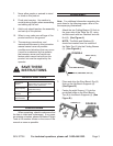
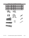
Turn the assembled Bench upside down.5.
Position the Diagonal Supports (7) so 6.
one end is against the longer cross
beam of Bench Support (4) legs. Then
align the other end so it is ush to the
wood edge next to the center gap of the
Short Bench Top (8). The two Diagonal
Supports (7) need to be attached at
opposite sides of the bench gap, using
three Screws (11) per Support. (i.e., one
support will be attached to one bench
slat, and the other bench slat will be
attached to the other bench support.
(See Figure C.)
NOTE: 7. There are no pre-drilled holes
for the Screws (11) in the bench slat
or Bench Supports (4). Instead, there
are guide marks in the wood to indicate
where the Screws must be inserted.
(See Figure C.)
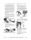
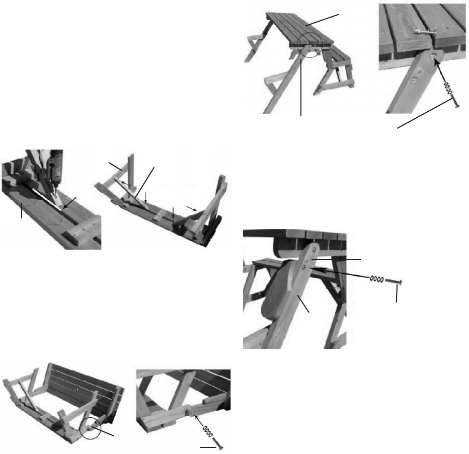
Set the Table on its side.8.
Attach the Folding Beams (2) to the 9.
outside edge of the Bench Supports (4),
using two Bolts, each with four Washers,
and one Nut (10).
(See Figure D.)
FIGURE D
BOLTS, WASHERS, NUTS (10)
FOLDING BEAM (2)
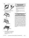
Hold the Table securely in its standing 10.
position.
Attach the two Table Legs (1) to the 11.
Table Top (5) by inserting two Bolts
each, with four Washers and one Nut
(10) into the pre-drilled hole at the
rounded end of the Table Legs. NOTE:
One pre-drilled hole still remains below
the Table Legs. (See Figure E.)
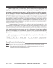
Attach the two Arm Rests (3) to the Table 12.
Legs (1), using two Bolts, each with four
Washers and one Nut (10). (See Figure
F.)
Place the Long Bench Top (6) on the 13.
Table Legs (1). Make sure the longer
bar underneath the Long Bench top is
toward the outside.
(See Figure G.)
Fasten the eight Screws (11) into the 14.
pre-drilled holes in the Long Bench Top
(6) to the Table Legs (1).
(See Figure G.)
FIGURE E
TABLE LEG
(1)
TABLE TOP (5)
BOLTS, WASHERS, NUTS (10)
FIGURE C
DIAGONAL
SUPPORT
(7)
BENCH
SUPPORT
(4)
SHORT
BENCH
TOP (8)
FIGURE F
BOLTS
WASHERS
NUTS
(10)
ARM
REST
(3)
TABLE LEG (1)