


Page 6
For replacement parts, please call 1-800-444-3353.
SKUs
91839, 91840
& 92199
Operation
Warning!! Always block the wheels before changing the
position (vertical/horizontal) of the unit.
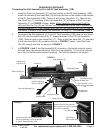
In FIGURE 1, the Rail Assembly (2) is shown in Horizon-
tal mode for operation and travel. In FIGURE 4 the unit
is shown in the vertical position. To change positions,
remove the Hair Pin Clip (29) and the Push Pin (26). A
close-up of this Push Pin (26) is shown in FIGURE 3 on
page 5. Tilt the unit to the vertical position as shown in
FIGURE 4, and replace both the Push Pin (26)
and the Hair Pin Clip (29) into the vertical posi-
tion hole (See FIGURE 1). Reverse the process
to return to the horizontal position.
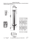
1. Remove the Oil Plug (37) and fill the tank with
Hydraulic oil (not included). To check the oil level remove the Dipstick (62), check the
level then replace it. The oil should be at the upper notch of the Dipstick. Be sure that
a constant oil level of 2.5 gallons is maintained. See FIGURE 3 on page 5, Parts List
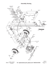
page 9, and Assembly Diagram page 10.
2. The hydraulic system must be vented during operation or it may become vacuum locked
and stop working properly. To vent the system, open the air inlet hole (See FIGURE
3) by loosening the Oil Plug. You may have to move the o-ring to expose the air inlet
vent. When the Log Splitter is not in operation or being transported, close the air inlet
hole by tightening the Oil Plug (37).
3. Make certain that the maximum length of each log does not exceed 25 inches with a
diameter of 8 inches.
Transportation
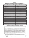
When transporting the Log Splitter, make sure
your hitch (not included) is compatible with the
Hitch Coupler (9). Follow all of the safety warn-
ings for towing in your vehicle’s manual. Always
use the Safety Chain with Hook (4) when towing
a vehicle. Do not tow the Log Splitter at speeds
above 45 MPH. As mentioned in number 2 on page 5, always travel with the Front Leg
Assembly (11) in the horizontal position. The Rail Assembly (2) must always be secured
in the horizontal position for travelling. Note: Make sure the air inlet hole on the Oil Plug
(37) is covered when transporting. See FIGURE 3 on page 5, and refer to number 2 in
Operation below.
Pull up and down on the Hitch Coupler to make sure the hitch ball is fitting snugly in the
Hitch Coupler. There should be no play between the hitch ball and Hitch Coupler. If there
is play, tighten the Adjustment Nut until no play is present. If the Adjustment Nut is too
tight, the Handle will not lock.
Note: The hitch will accept 2 inch hitch balls.
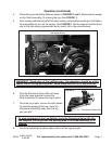
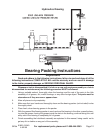
FIGURE 4
Vertical Position
Place
Log
Here
Base
CAUTION
Care must be taken when backing up
the Trailer; only back up the trailer on a
straight path. If the Trailer is allowed to turn
off the straight path while backing up, the Trailer
could jackknife, causing severe damage to the
trailer and to the towing vehicle.
REV 07e