


Page 4
SKU 90757
Assembly and Operation
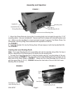
FIGURE 1
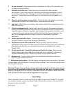
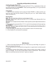
1. Mount the Shear Brake by driving the 4 mounting bolts (not included) through the 11/16”
mounting holes, into your workbench. Secure each bolt in place with included washer and
nut. Make sure the workbench is level and solid enough to support the Brake Shear, the
workpieces, and the pulling force associated with operation of the tool.
See FIGURE 1.
2. Insert the Handle (31) into the Driving Gear (30) and secure it with the Handle Bolt (29).
See FIGURE 1.
Inserting the Lower Bending Die (2)
Note: The Lower Bending Die (2) is reversible and can be inserted using either the top or
bottom, depending on the thickness of the metal you are working with.
1. To insert the Lower Bending Die 2, slide the smaller end first, into the bottom of the ma-
chine as shown in FIGURE 2. The rear side of the Lower Bending Die (2) is shown on the
back side of the Shear Brake in FIGURE 1. Make sure the Lower Bending Die (2) lines up
with the upper Dies (3, 37-41). FIGURE 3 shows the front side of the unit with the Lower
Bending Die (2) installed.
Handle (31)
Handle Bolt (29)
Driving Gear (30)
Mounting Hole
Mounting Hole
Rear side of
Lower Bending Die (2)
Front Side of
Lower Bending Die (2)
FIGURE 2 FIGURE 3
Lower Bending Die (2)
Bolt (5)
Cutting
Slot
Jaw Opening
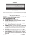
REV 03/04