


SKUs 04815, 91013, 90860, & 90717 Page 6
3.
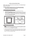
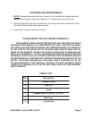
To secure the two angle brackets to the mounting surface,
drill two 1/4” holes though
the base of each angle bracket. Then, drill four 1/4” holes, appropriately spaced, through
the mounting surface. Use four screws, lock-washers, and nuts (not provided). (See
Figure C.)
To Connect The Solar Panel To The Charge Controller:
Note: An appropriate charge controller must be used to prevent overcharging,
damage to the battery, and other problems-see warning 8 on page 4 for details.
1. CAUTION: Do not cross electrical polarity, as product damage and/or personal
injury may occur. The Solar Panel junction box contains a terminal strip with two
active positions. The terminal with the RED lead attached is “POSITIVE”. The
terminal with the BLACK or BLUE lead attached is “NEGATIVE”.
WHEN IN
DOUBT, TEST WITH A VOLTMETER.
2. Typical connection instructions. ALWAYS refer to the manual for the charge controller
that you will use for correct procedures.
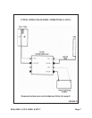
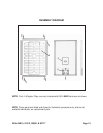
a. To connect the two leads from
one
Solar Panel to the charge controller (not
provided) to get 12 Volt output, see Figure D on page 7.
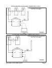
b. To connect the two leads from
multiple
Solar Panels to the charge controller to
get 12 Volt output, see Figure E on page 8.
c. To connect the two leads from
two
Solar Panels to the charge controller to get 24
Volt output, see Figure F on page 8.
3. Once the two leads are completely connected to the charge connector, refer to the
“Specifications” section of this manual to determine the
charging time
required
for the specific model of Solar Panel you are using.
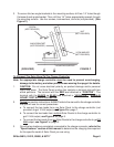
SCREW
(NOT PROVIDED)
LOCK WASHER
(NOT PROVIDED)
ANGLE BRACKET
(NOT PROVIDED)
(SIDE VIEW)
FIGURE C
MOUNTING SURFACE
NUT
(NOT PROVIDED)