


6.
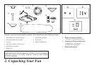
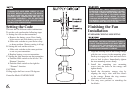
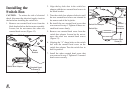
Setting the Code
This unit has 16 different code combinations.
To set the code, perform the following steps:
A. Setting the code on the transmitter:
a. Remove the battery cover. Press rmly
below arrow and slide battery cover off.
b. Slide code switches to your choice of up
or down position. (Factory setting is all up).
B. Setting the code on the receiver.
a. Slide code switches to the same position
as set on your transmitter.
b. Replace battery cover on transmitter.
C. Setting the light function on the transmitter.
a. Push the black switch to the left for “No
Dimmer” function.
b. Push the black switch to the right for
“Dimmer” function.
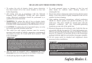
CAUTION:
Ceiling angle shall not exceed 30 degrees.
Controller Model: FAN28R-240W
EACH WIRE NUT (WIRE CONNECTOR) SUP-
PLIED WITH THIS FAN IS DESIGNED TO ACCEPT
UP TO ONE 12 GAUGE HOUSE WIRE AND TWO
WIRES FROM THIS FAN. IF YOU HAVE LARGER
THAN 12 GAUGE HOUSE WIRING OR MORE
THAN ONE HOUSE WIRE TO CONNECT TO THE
FAN WIRING, CONSULT AND ELECTRICIAN FOR
THE PROPER SIZE WIRE NUTS TO USE.
THE FREQUENCIES ON YOUR RECEIVER AND
TRANSMITTER HAVE BEEN PRESET AT THE
FACTORY. BEFORE INSTALLING THE RECEIV-
ER, MAKE SURE THE DIP SWITCHES ON THE
RECEIVER AND TRANSMITTER ARE SET TO
THE SAME FREQUENCY. THE DIP SWITCHES
ON THE TRANSMITTER ARE LOCATED INSIDE
THE BATTERY COMPARTMENT.
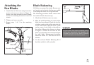
Finishing the Fan
Installation
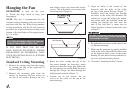
STANDARD CEILING MOUNTING
Align the locking slots of the ceiling canopy 1.
with the two screws in the mounting plate.
Push up to engage the slots and turn clock-
wise to lock in place. Immediately tighten
the two mounting screws rmly.
Install the remaining two mounting 2.
screws into the holes in the canopy and
tighten rmly.
Install the decorative canopy ring by 3.
aligning the ring’s slots with the screws
in the canopy. Rotate the ring counter-
clockwise to lock in place.
You may now proceed to attaching the 4.
fan blades.
WHEN USING THE STANDARD BALL/DOWNROD
MOUNTING, THE TAB IN THE RING AT THE BOT-
TOM OF THE MOUNTING PLATE MUST REST IN
THE GROOVE OF THE HANGER BALL. FAILURE
TO PROPERLY SEAT THE TAB IN THE GROOVE
COULD CAUSE DAMAGE TO WIRING.
Figure 9