


7
Section 2 – Operation
Recreational Vehicle Generator
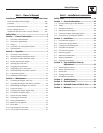
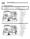
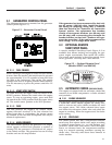
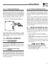
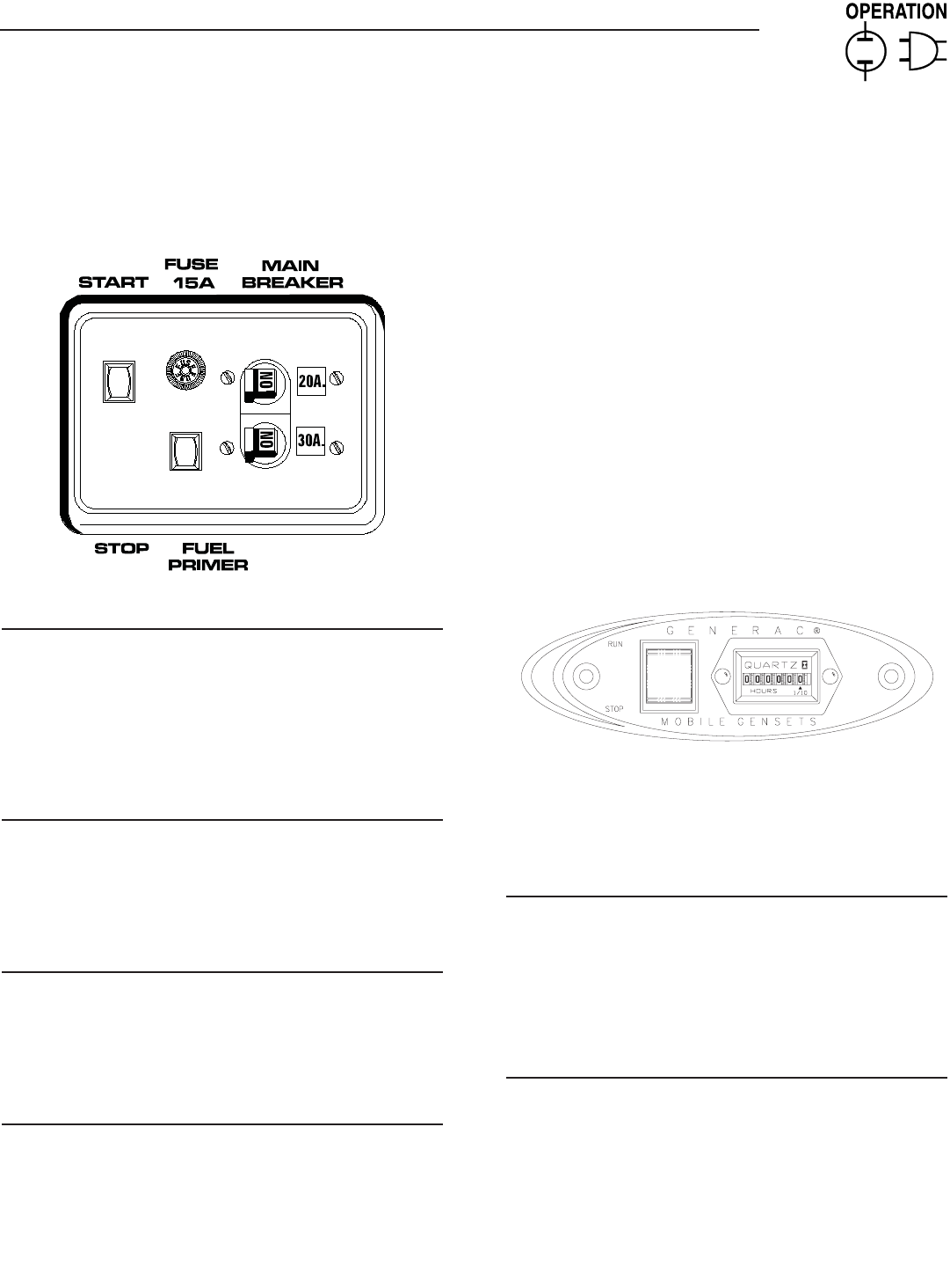
2.1 GENERATOR CONTROL PANEL
The following features are mounted on the generator
control panel (Figure 2.1):
Figure 2.1 – Generator Control Panel
2.1.1 FUEL PRIMER
Before starting a cold engine (if it has not been started
in more than two weeks), this switch must be pressed
for approximately 10 to 15 seconds to bring fuel from
the tank to the carburetor. This rocker type switch
springs back into its original position when released.
It is not necessary to press the primer switch for LP
units.
2.1.2 START/STOP SWITCH
To crank and start the engine, hold this switch in the
START position. Release the switch when the engine
starts. To stop an operating engine, press and hold
the switch in the STOP position until the engine shuts
off. The switch center position is the RUN position.
2.1.3 FUSE
The fuse protects the engine’s DC control circuit
against electrical overload. If the fuse element has
melted open due to overloading, the engine cannot
be cranked. If the fuse must be replaxed, use only an
identical replacement.
2.1.4 MAIN BREAKER
The main breaker protects the generator’s AC output
circuit against overload and provides a method of
turning OFF the generator’s 120/240-volt AC output
to the vehicle circuits. The generator has one 20-amp
breaker and one 30-amp breaker.
NOTE:
If the generator has been reconnected for dual volt-
age AC output (120/240 volts), install line break-
ers having an amperage rating that is different
than that stated in the "Generator AC Connection
System" section. The replacement line breakers
consist of two separate breakers (one 20 amp, and
one 30 amp) with a connecting piece between the
breaker handles (so that both breakers will oper-
ate at the same time). If the unit is reconnected for
dual voltage, it is no longer RVIA listed.
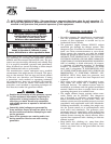
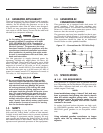
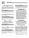
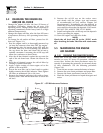
2.2 OPTIONAL REMOTE
START/STOP PANEL
A remote mounted Start/Stop Panel (Figure 2.2) is
available that allows starting and stopping the gen-
erator engine conveniently from inside the vehicle.
The remote panel includes a Start/Stop switch, hour-
meter, generator run lamp and a wire harness.
Figure 2.2 — Optional Remote Panel
(Models 004057 and 004184)
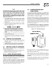
2.3 AUTOMATIC CHOKE
(GASOLINE ONLY)
The engine is equipped with an automatic choke that
consists of two main components: a choke solenoid
and prechoke.
2.3.1 CHOKE SOLENOID
During engine cranking (Start/Stop switch at START),
a solid-state choke module signals the choke sole-
noid to activate and cycle (choke on/choke off) until
the engine starts. The choke solenoid thus opens
and closes the carburetor choke valve only when the
engine is cranking. When the engine starts, the choke
stops cycling.
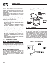
2.3.2 PRECHOKE
The choke system also has a temperature-sensitive
metal strip that adjusts choke valve angle according
to ambient temperatures (i.e., in cold ambient tem-
peratures, choke valve closes more). Once the engine
starts, an element heats the temperature-sensitive
strip to a normal operating condition, opening the
choke valve. This may take about three minutes in
cooler weather.