


32
2.7.2 WIRING
Wiring should be of stranded copper to reduce the
chance that vibration may cause breakage.
Wire gauge size should be large enough to handle at
least 115 percent of the installed generator's rated
maximum current.
If neutral conductors are used, they must be the
same size as other leg wires.
Route power supply conductors from generator AC
output leads T1 (red), T2 (white), T3 (black) and
the green ground wire through approved flexible
conduit to the electrical junction box on the com-
partment wall.
If flexible metal conduit is used between the genera-
tor and the compartment junction box, the conduit
end that terminates the compartment junction box
must be vapor-sealed. Flexible metal conduit is NOT
vapor tight along its entire length.
From the junction box, route power supply wires
through approved conduit to either (a) double-pole,
double-throw transfer switch, or (b) approved isola-
tion receptacle. Connecting to a transfer switch or
isolation receptacle must prevent vehicle electrical
circuits from being connected to two different power
supplies at the same time (such as generator and
dockside power).
Conductors must be rated 221° F (105° C) or must
be of a larger conductor size.
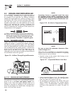
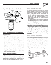
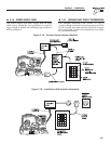
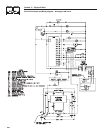
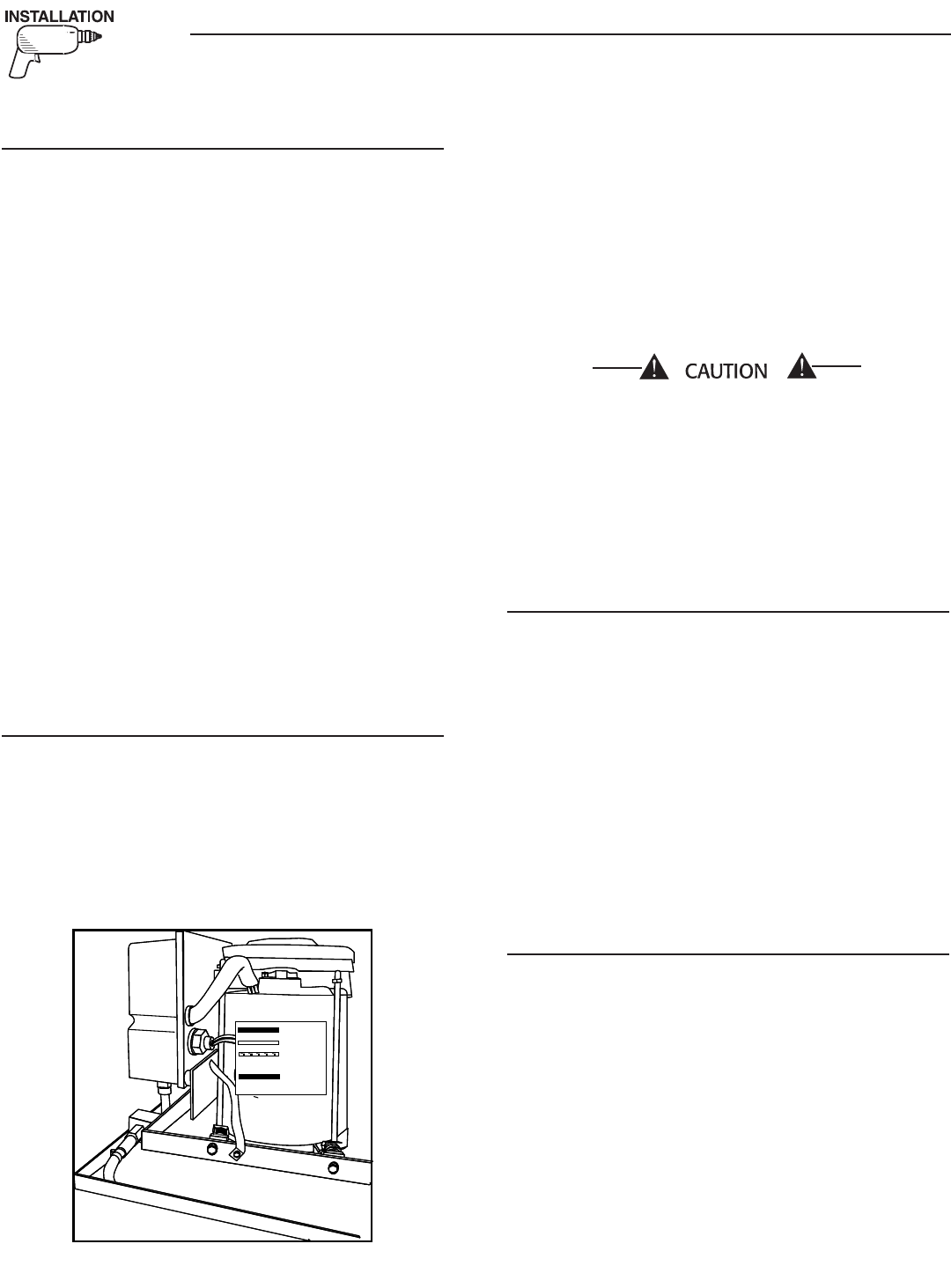
2.7.3 GENERATOR AC CONNECTIONS
Generator AC output leads T1 (red), T2 (white) and
T3 (black) come out of the generator as shown in
Figure 2.17. Leads T1 (red) and T3 (black) are “hot,”
while T2 (white) is the grounded neutral lead. There
is also a green lead that connects to ground in the
junction box of the recreational vehicle.
Figure 2.17 – Generator AC Output Leads
T3
T2
T1
Green
(Ground)
•
•
•
•
•
•
•
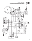
Line T1 (red) to T2 (white) is protected against
overload by a 30-amp circuit breaker (CB1). Use
this line-to-neutral connection separately to operate
120-volt, single-phase, 60 Hertz, AC loads requiring
up to 3,600 watts (3.6 kW) of power. Line T3 (black)
to T2 (white) also is protected against overload by a
20-amp circuit breaker (CB2). Use this line-to-neu-
tral connection separately to operate similar loads.
However, be sure the total unit load does not exceed
the maximum rating of the generator. The neutral line
(T2, white) on all units is a grounded neutral.
Do NOT connect electrical loads in excess of any
circuit breaker rating or problems with circuit
breaker tripping will develop, which causes a loss
of AC output. Also, do NOT exceed the generator's
rated wattage capacity. Add the watts or amperes
of all lighting, appliance, tool and motor loads
the generator will operate at one time. This total
should be less than the unit's rated wattage/
amperage capacity.
2.7.4 CONDUIT
Route the connections between the generator and the
junction box through approved, flexible conduit. The
following general rules apply:
Cut wiring to the required length and allow extra
wire for junction box connections.
Carefully prepare conduit ends to prevent sharp
edges from cutting through wiring insulation.
Route conduit so it does not interfere with genera-
tor movement.
If using metallic conduit, vapor seal the end of the
conduit where it enters the junction box. Do this
because flexible metallic conduit is not vaporproof
along its entire length.
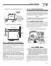
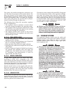
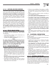
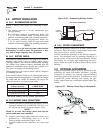
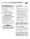
2.7.5 ISOLATING DIFFERENT POWER
SOURCES
Connections from the junction box must terminate in
a double-pole, double-throw transfer switch (Figure
2.18). An alternate method for isolating different
power sources is by using an isolating receptacle
(Figure 2.19). Whichever method is use, be certain
that both power sources are NOT connected at the
same time.
•
•
•
•
Section 2 – Installation
Recreational Vehicle Generator